SM471_Introduction(Chi_Ver1).pdf - 第60页
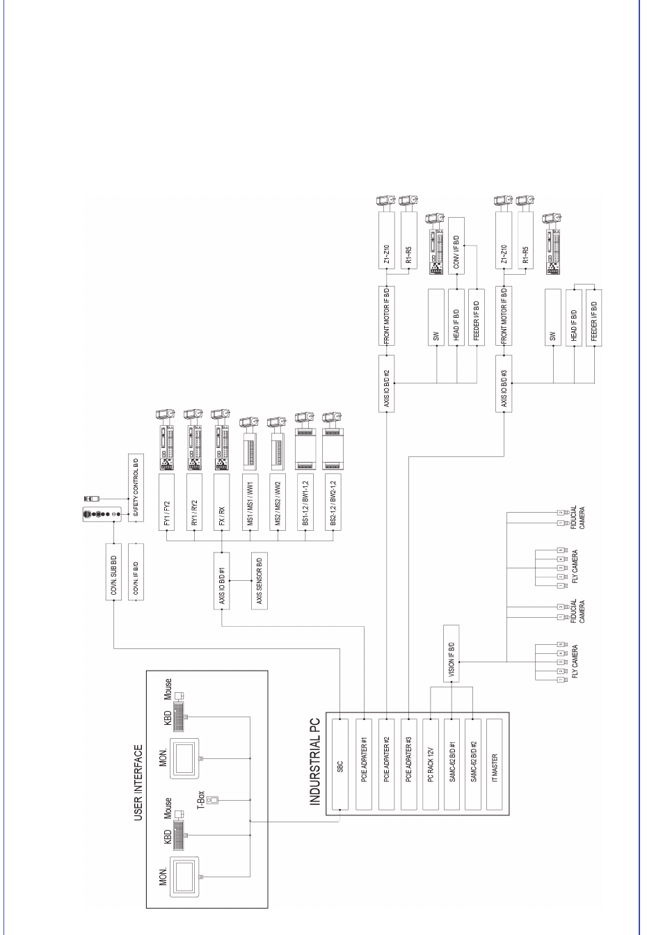
3-4 Samsung Component Placer S M471 Introduction 3.2.2. 控制部分的构成 图 3.3 控制部分的结构图
3-3
设备的名称及构成
3.2. 系统的构成
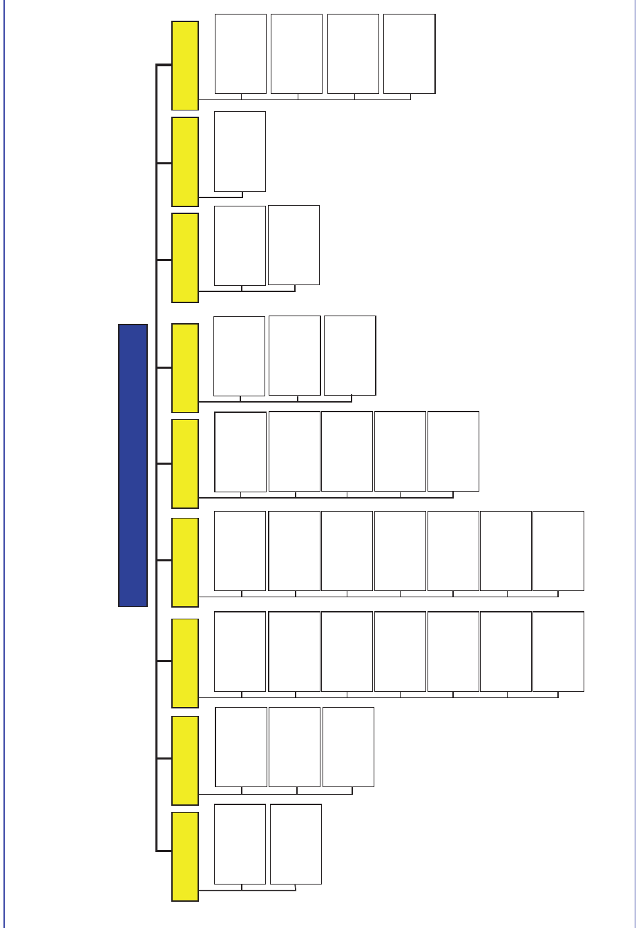
3.2.1. 机械部分的构成
图
3.2
机械部分的结构图
Mechanical Part Confuguration of SM471
Mechanical Part Confuguration of SM471
Main Frame XY Gantry Head1 Cover
Feeder Base ANC
Conveyor&BUT
Base Frame
Electrical Unit
. Control Part
. Drive Part
Z Axis (20Axis)
. Motor
. Spline
Theta Axis
(10 Axis)
. Motor
Theta Axis
(10 Axis)
. Motor
Z Axis (20 Axis)
. Motor
. Spline
S Axis (2 Axis)
. Motor
S Axis (2 Axis)
. Motor
Flying Camera
.
FOV 24mm
.
FOV 24mm Mega
Pixel Cam. (Option)
Flying Camera
.
FOV 24mm
.
FOV 24mm Mega
Pixel Cam. (Option)
Nozzle
Pneumatic
Fiducial
Camera
Head2
Nozzle
Fiducial
Camera
X-Gantry1
. Motor/Encoder
. Frame
X-Gantry2
. Motor/Encoder
. Frame
Y Axis
. Motor/Encoder
. Frame
Work Station
.Width Control
Entry Shuttle
Exit Shuttle
Electrical
Module
Backup Table
Extemal
Cover
Operation
Panel
Acrylic
Window
Front
Rear
Docking Cart
Feeder Base
(Option)
Front
Rear
Pneumatic
System
Mist Seperate
Pressure
Gauge
Regulater
Manifold
Pneumatic
3-4
Samsung Component Placer SM471 Introduction
3.2.2. 控制部分的构成
图
3.3
控制部分的结构图
3-5
设备的名称及构成
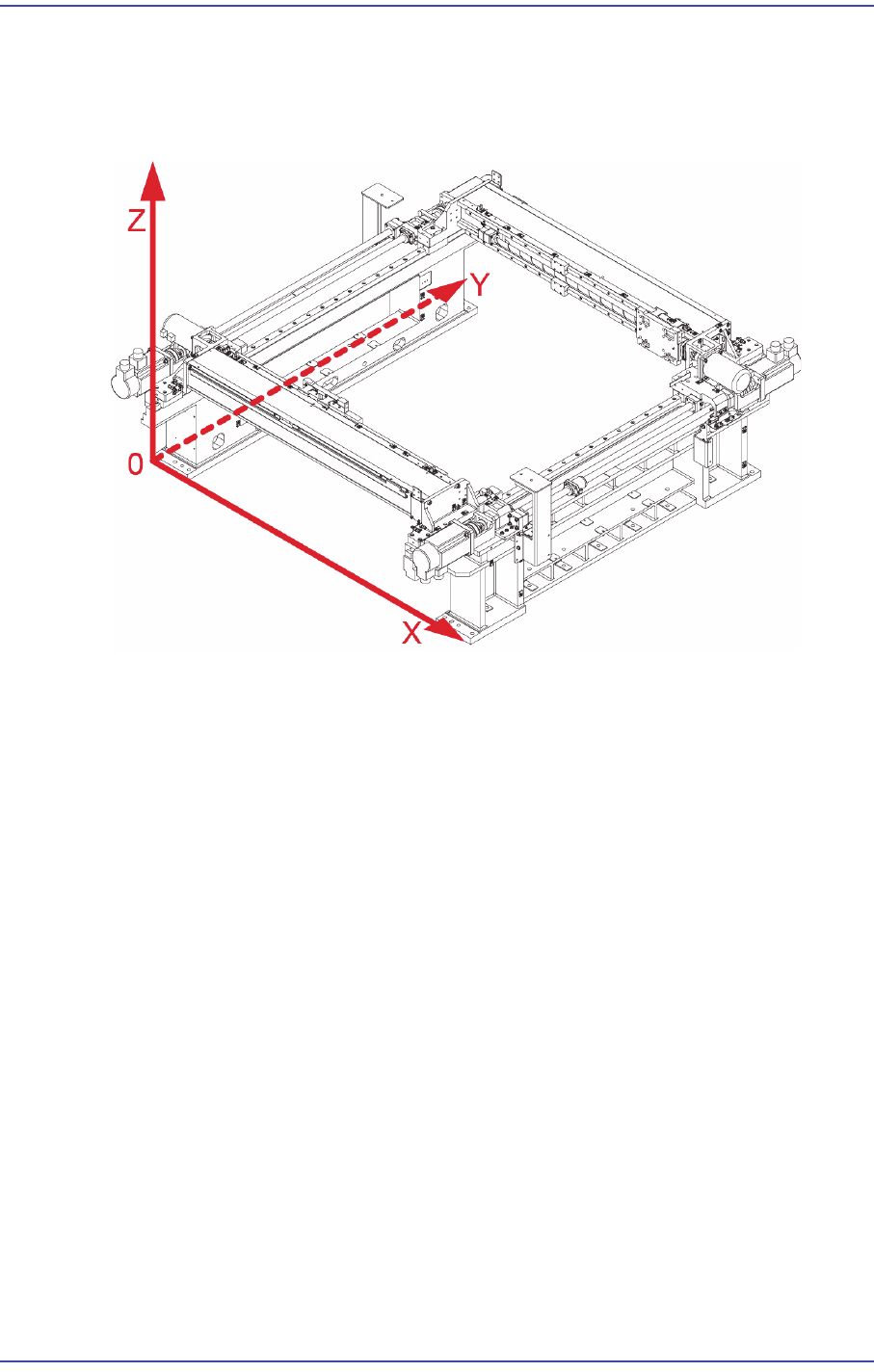
3.3. 坐标系
本设备基本的坐标系如以下”
图
3-4”所示。
图
3.4
设备的坐标系
3.3.1. X, Y轴
表示Head, ANC, 贴装点(Placement Position), PCB的基准点标记(Fiducial Mark)的
位置。
3.3.2. Z 轴
Z轴表示从Head到吸嘴尾端的位置,把固定基板的上面位置作为0。