00193730-04.pdf - 第32页
Retrofit instructions Splice Detection Basic Package + Tab le Controller SIPLACE HF-series 08/2005 Edition 32 There is a hole in the front p art of the bracket (see photogra ph above). In the wall behind it, there may o …
Retrofit instructions Splice Detection Basic Package + Table Controller SIPLACE HF-series
08/2005 Edition
31
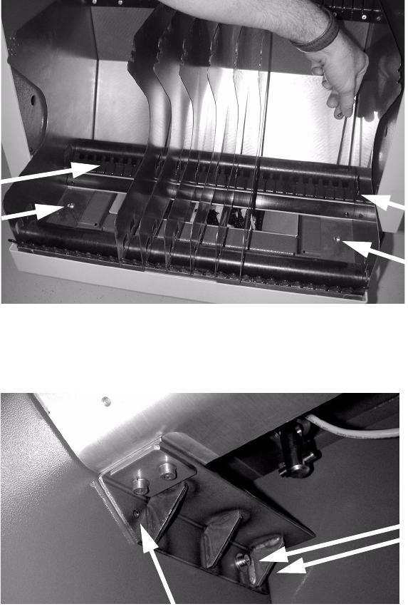
: Unscrew the four screws used to fix the tape reel container and remove the container.
2
2
: Position the brackets at right-angles to the partition and fix them loosely with two screws.
2
2
: Place the adapter (third tape reel) on the bracket and check the position with a spirit level.
Tighten the screws in the brackets if the adapter is straight.
2
2 screws
Hole in the bracket
Retrofit instructions Splice Detection Basic Package + Table Controller SIPLACE HF-series
08/2005 Edition
32
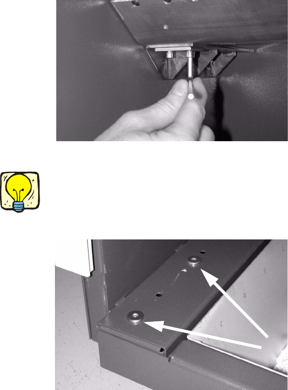
There is a hole in the front part of the bracket (see photograph above).
In the wall behind it, there may or may not be a hole with welding nut behind it, depending on which
component trolley is used. 2
: If there is a hole, then screw in a screw (M 6) to match the two others.
: If there is no hole, then drill a 6.2 mm diameter hole from the fitted bracket.
: Push a grooved dowel pin, external diameter 6.5 mm, into the drilled hole.
The grooved pin will thus be seated firmly.
: Fix the adapter with two screws on each side.
2
: Position the plain washers on the screw holes for the tape reel container.
2
If you fix the plain washers in place with adhesive tape, they will not slip when you position the
tape reel container. 2
2
2
: Refit the tape reel container, offset 110 mm forward.
: Insert the tape separators once more.
: Push the waste tape container beneath the component trolley.
Retrofit instructions Splice Detection Basic Package + Table Controller SIPLACE HF-series
08/2005 Edition
33
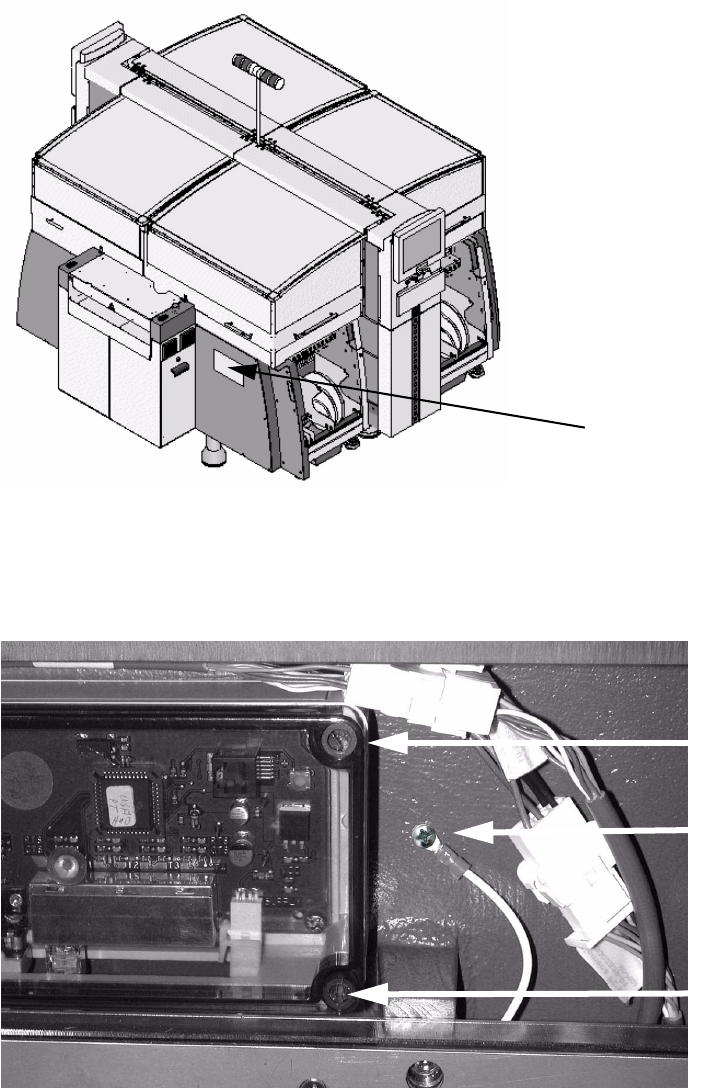
2.9 Installing the basic package and connecting the
communication interface
2
: Use four screws to screw the communication interface to the machine base.
The screw holes are predrilled (see photo below).
: Screw the ground connection with a Phillips screw.
2
Assembly position for
the communication
interface
Ground
Screw
Screw