Technical_reference.pdf - 第102页
Technical Service Manual 102 Revision Dat e: August 2004 REPLACING T HE ACTUAT OR ASSEMBLY W ITH THE BO NNET IN T HE CLOSED POSIT ION : Remove the bonnet br idge sheet m etal piece on the end of the oven where the actuat…
Technical Service Manual 101 Revision Date: August 2004
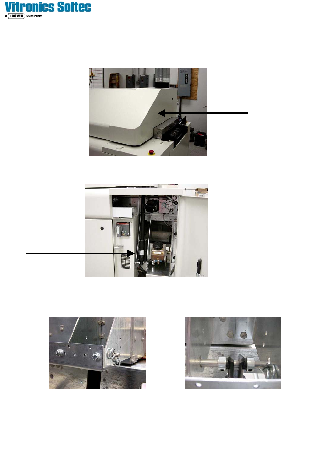
Remove the two safety clips from the pin holding the actuator piston to the bracket. Remove the piston pin holding the
actuator piston to the bracket.
The installation procedure is the reverse if the removal procedure.
Technical Service Manual 102 Revision Date: August 2004
REPLACING THE ACTUATOR ASSEMBLY WITH THE BONNET IN THE CLOSED POSITION:
Remove the bonnet bridge sheet metal piece on the end of the oven where the actuator will be changed.
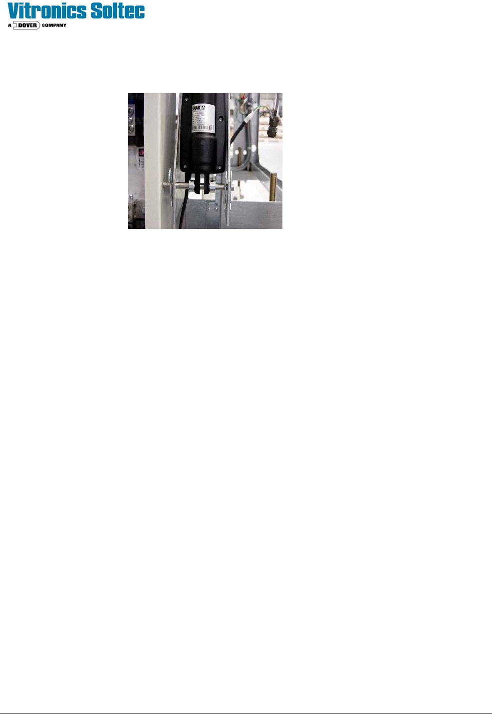
The body of the actuator is accessed through the equipment cabinets on each end of the oven.
Carefully raise the actuator and position it in its frame location. Use the mounting pin to lock the piston in place in the
bracket. As you are pushing the mounting pin into place, install the locking shaft collars on each side of the piston.
Replace the two safety clips on the mounting pin. Let the actuator hang from the mounting pin.
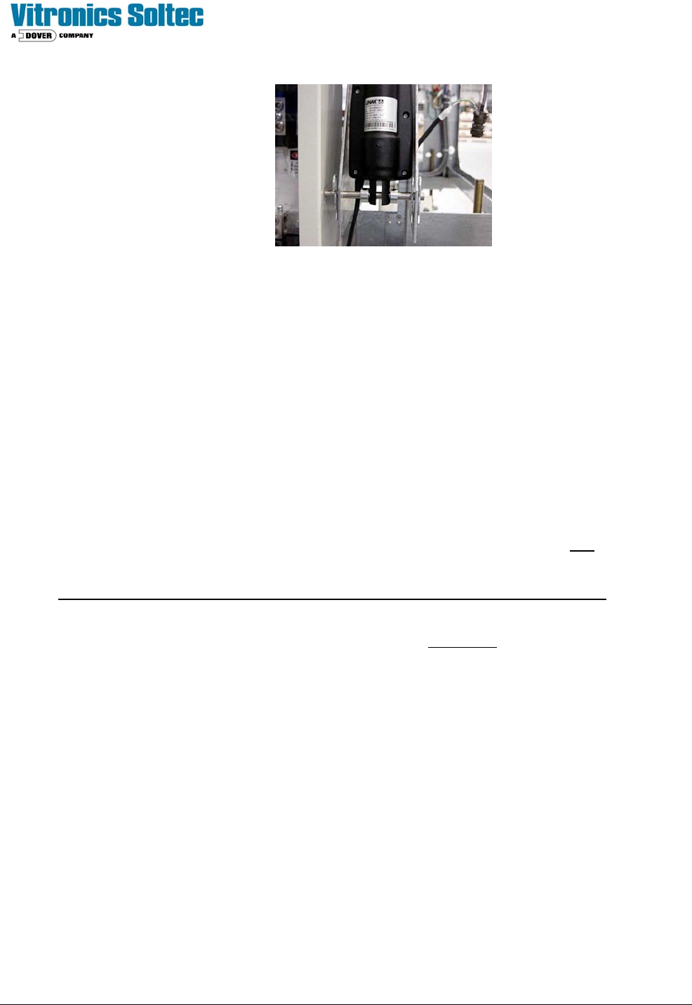
Carefully position the actuator so that the holes for the actuator pivot pin are aligned with the holes in the side of the
actuator sheet metal. Insert the actuator pivot pin. As you are pushing the mounting pin into place, install the locking
shaft collars on each side of the piston. Replace the two safety clips on the mounting pin. Let the actuator hang from the
Technical Service Manual 103 Revision Date: August 2004
mounting pin.
Plug the control cable of the new actuator to the control box. Turn power on to the oven so the actuator can be operated.
Perform the actuator set-up and synchronization at this time.
The installation procedure is the reverse of the removal procedure.
SET-UP AND SYNCHRONIZATION OF THE LINAK ACTUATORS:
The actuators are installed and synchronized on the oven when it is built.
Caution Notes:
The following process is used for two or three actuators on the same oven, and is required only after replacement of an
actuator or control box, or if an actuator is out of adjustment.
1. Do not turn the spindle while the actuator is plugged into the actuator control box. This will send
erroneous pulses to the control box causing misalignment and possible damage to the system. For initial factory
set-up or field replacement, the spindle may be turned no more than three revolutions to align the clevis pin hole
to the bracket. This must only be done when the actuator is unplugged from the control box.
2. Do not unplug the actuator from the control box during operation or in an attempt to adjust or synchronize the
actuators. This will cause misalignment resulting in possible damage to the system.
3. Raising or lowering one side of the heat zone more than the prescribed distance may cause structural damage to
the system.