Technical_reference.pdf - 第125页
Technical Service Manual 125 Revision Dat e: August 2004 SETUP The SMEMA interf ace requir es that the connec tions be m ade between adjoining m achines and the Ref low Oven, using the SMEMA connectors at the onload and …

Technical Service Manual 124 Revision Date: August 2004
SMEMA INTERFACE
The SMEMA Interface is:
! Standard, (installed on all ovens) ) An option, (NOT installed on all ovens)
DESCRIPTION
(SMEMA is the acronym for Surface Mount Equipment Manufacturer’s Association)
The SMEMA electrical interface option for the Reflow Oven is intended to comply with the SMEMA Electrical Interface
Standard 1.2. It provides signals from the Reflow Oven to the upline/downline equipment in the process line.
A PLC is mounted inside the electrical enclosure; a photo-sensor is mounted on brackets above each end of the
conveyor(s). A 14 pin round connector is mounted on each end of the Reflow Oven. The SMEMA interface receives
power from the Reflow Oven to operate. (The PLC operates two SMEMA circuits.) The SMEMA interface accepts a
'Board Available' signal from the upline (onload side) of the Reflow Oven on pins 3&4 of the onload connector. It replies
with a 'Busy' signal on pins 1&2 of the onload connector to the machine upline. On the downline (offload) side, a 'Board
Available' signal is sent on pins 3&4 and looks for a 'Busy' signal to come back on pins 1&2 of the offload connector.
Because the Reflow Oven should not be stopped with product in the heat zone, the busy signal coming from the downline
end is used to generate the busy signal for the upline equipment without stopping the Reflow Oven. When all of the
conditions are ‘False’, the Reflow Oven is “not busy” and will accept more product from the upline equipment. If any of
the conditions are ‘True’, the Reflow Oven will transmit a "busy" signal to the upline equipment. This should stop the
upline equipment from sending product to the Reflow Oven, thus preventing a product buildup.
The upline “busy” signal can be a result of one (or more) of the following:
1. Board at ‘on-load’
2. Board Jam at off-load
3. Downline machine has not sent ‘ready’ signal for 2 boards
4. Oven is NOT ‘Process Ready’
5. The (settable) spacing between boards has not been satisfied.
The busy signal from the Reflow Oven to the upline piece of equipment is designed to provide a space equal to
approximately 1/2 the product length between each product under normal operation. The board available signal sent from
the upline equipment is not implemented because the oven should not be stopped and started. The board available signal
sent from the Reflow Oven to downline equipment is a notification of product coming out of the oven.
When a board's leading edge passes under the onload sensor it triggers the busy signal to be true (on) for 1.5 board
lengths. This tells the upline equipment feeding the Reflow Oven to wait for 1.5 board lengths before feeding another
piece to the Reflow Oven. When the board exits the oven and the leading edge passes under the offload sensor, it
triggers the board available signal to go true (on) 1 second later and to stay true for one board length. This signals the
downline equipment receiving product from the Reflow Oven to expect a board at that time. The 1-second delay is to
ignore false signals created when the photocell senses the conveyor belt.
The PLC controls the delays and triggers the operation of the interface off of the process ready signal. If the machine is
NOT process ready, the SMEMA interface will signal busy to the upline equipment.

Technical Service Manual 125 Revision Date: August 2004
SETUP
The SMEMA interface requires that the connections be made between adjoining machines and the Reflow Oven, using
the SMEMA connectors at the onload and offload ends. The PLC is pre-programmed and the sensors are preset at the
factory. The SMEMA interface is installed and fully tested at the factory before shipping. The user should not need to
adjust the SMEMA interface after initial connections have been made.
OPERATION
Action by the Reflow Oven operator is not necessary for the SMEMA interface to function. As long as the upline /
downline connections are made and a component failure has not occurred, operation will be automatic when the Reflow
Oven is powered up.
NOTE
Ovens with a Dual Rail conveyor (with two sets of rails and chains) have two separate sets SMEMA Interface sensors
making separate input(s) to the PLC.
Each conveyor must be ready to receive product before it independently sends a “Ready” signal to its respective “upline”
equipment.
Either conveyor can send a “Product at Offload” signal to the “downline” equipment.
Technical Service Manual 126 Revision Date: August 2004
SMEMA machine interface
for Vitronics SMEMA04 January 22, 2004
using the Allen Bradley MicroLogix 1200 PLC.
There are two test procedures below. The first test is for PLC units that are installed in an oven, and the second is for
PLC units being tested separately from the oven (stand-alone). The stand-alone test specifies input and output
connections instead of devices (sensors, upstream / downstream machines, etc.). The tests are otherwise identical.
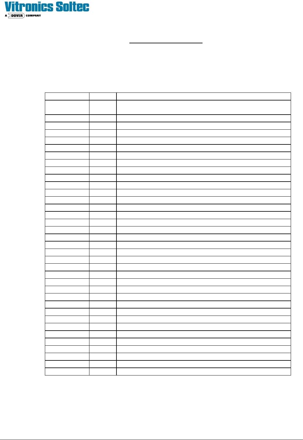
Allen Bradley MicroLogix 1200
PLC Terminal Connections
PLC terminal Wire # Description
24 COM 2007 DC common from PLC, On-load (SX200-4,SX201-4), Off-load
(SX202-2,SX203-2)
24 VDC 2003 24VDC from PLC, COM 0, COM 1
IN 0 - Not used
IN 1 2008 On-load lane #1 product sensor
IN 2 2038 On-load lane #2 product sensor
IN 3 2009 Oven ready
IN 4 2018 Off-load lane #1 product sensor
IN 5 2048 Off-load lane #2 product sensor
IN 6 2014 Downstream machine lane #1 ready (SX202-1) W189A
IN 7 2044 Downstream machine lane #2 ready (SX203-1) W189B
IN 8 - Not used
IN 9 - Not used
IN 10 - Not used
IN 11 - Not used
IN 12 - Not used
IN 13 - Not used
COM 0 2003 Input common for IN 0 through IN 3 (24VDC)
COM 1 2003 Input common for IN 4 through IN 13 (24VDC)
L1 18 115 VAC hot
NEUT 2 115 VAC neutral
G G Protective ground
DC 0 2020 Output common for OUT 0 (SX200-1) W190A
OUT 0 2022 Oven ready to upstream lane #1 (SX200-2) W190A
DC 1 2040 Output common for OUT 1 (SX201-1) W190B
OUT 1 2042 Oven ready to upstream lane #2 (SX201-2) W190B
DC 2 2021 Output common for OUT 2 and OUT 3 (SX202-3) W189A
OUT 2 2023 Product available to downstream lane #1 (SX202-4) W189A
OUT 3 - Not used
DC 3 2051 Output common for OUT 4 and OUT 5 (SX203-3) W189B
OUT 4 2053 Product available to downstream lane #2 (SX203-4) W189B
OUT 5 - Not used (Always on when PLC is in run mode)
DC 4 - Output common for OUT 6 through OUT 9
OUT 6 - Downstream lane #1 alarm (product jam or not ready)
OUT 7 - Downstream lane #2 alarm (product jam or not ready)
OUT 8 - Not used
OUT 9 - Not used