00193733-02.pdf - 第50页
2 Assembly Instructions PCB Camera, Multicolor SIPLACE F5 HM SIPLACE F5 HM 2.2 Safety Instructions 05/2007 Edition 50 Observe the guidelines of the Main Associat ion of the German T rade Association, VBG 93. In all other…
SIPLACE F5 HM 2 Assembly Instructions PCB Camera, Multicolor SIPLACE F5 HM
05/2007 Edition 2.2 Safety Instructions
49
2.2.2 Safety Notes about Laser Radiation
DANGER from laser radiation
2
Do NOT change or manipulate the safety equipment or the PCB camera Multicolor itself. The
LED illumination device for the PCB camera Multicolor complies with laser class "1M" without
any protective measures.
With protective measures, i.e., installing it in the machine properly, the PCB camera Multicolor
complies with laser class "1".
With this laser class, no laser warning signs are required on the machine (on the safety hoods) or
on the camera itself.
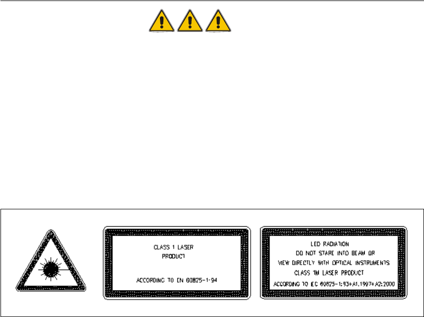
It is sufficient if the signs identifying the laser class and "1" and "1 M" are in the User Manual, as
shown below.
Abb. 2.2.1 Laser Warning Signs in the User Manual in the Pertinent National Language
2
Classifying the PCB camera Multicolor as laser class "1M" or "1" only applies if no one manipula-
ted with the camera. Make certain that the lacquer on the setting potentiometer on the camera and
on the "PCB camera board modular" is undamaged.
Otherwise there will be a higher risk of an accident due to LED radiation and it is not allowed to
install/continue to operate the PCB camera Multicolor in its current condition. 2
Cameras with a damaged seal must be returned to Siemens. 2
The voltage for the LED illumination of the PCB camera Multicolor is integrated into the safety cir-
cuit. It is switched off automatically when a protective cover is opened, EMERGENCY OFF is trig-
gered or the component changeover table on the machine frame is unplugged (interface cable).2
With "Key-operating switch in service position" the protective function (= shut-off of the LED
camera illumination) is retained. During the assembly the final safety check has to be carried out,
as described in Abschn. 2.11.
Rules for Germany:
2 Assembly Instructions PCB Camera, Multicolor SIPLACE F5 HM SIPLACE F5 HM
2.2 Safety Instructions 05/2007 Edition
50
Observe the guidelines of the Main Association of the German Trade Association, VBG 93.
In all other countries, comply with the pertinent guidelines and standards of the specific countries
in question.
Standards to be observed:
IEC 60825-1, EN 60825-1.
2
2.2.3 Definitions
DANGER
in terms of these instructions means that death, severe bodily injury or considerable material da-
mage WILL occur if the instructions about danger are not followed.
2
WARNING
in terms of these instructions means that death, severe bodily injury or considerable material da-
mage may occur if the warnings are not heeded. 2
CAUTION
in terms of these instructions mean that minor bodily injury or material may occur if the cautions
are not heeded. 2
NOTE
in terms of these instructions is a statement of important information about the product or the
pertinent portion of the instructions to which particular attention is being drawn. 2
2

SIPLACE F5 HM 2 Assembly Instructions PCB Camera, Multicolor SIPLACE F5 HM
05/2007 Edition 2.3 Requirements
51
2.3 Requirements
– Software version 407.01 or later.
2.4 Assembly Kits, Tools
2.4.1 Assembly Kit "PCB Camera Multicolor F5 HM"
1 Unit Assembly kit "Multicolor for F5 HM", item no.: 00358028-01, consisting of: 2
- PCB camera Multicolor Item no. 00355462-01 1 unit
- Assembly kit V50 currency Item no. 00357863-01 1 unit
2.4.2 Additional Material Required
- Cable tie L x W = 140 x 3.6 mm Item no.: 00805141-01 x units
- Cable clamp, size 6. Item no.: 00805503 8 units
- Aderendhülsen xxxxxxxx 5 units
NOTE:
No additional screws are needed to mount the PCB camera Multicolor. The captive screws are on
the PCB camera Multicolor. 2
2.4.3 Tools, Auxiliary Test Equipment and Expendable Materials
– Set of Allen wrenches
– Oblique-nosed cutting pliers
– Wire stripper
– ESD bracelet
– Small mirror to be used as an aid while installing/removing the PCB camera