ASM_Guide To Adhesive Dot Dispensing_Stinger_en_0321_online.pdf - 第10页
2 STINGER, A GUIDE TO ADHESIVE DOT DISPENSING 2.2 INTRODUCTION 10 GUIDE TO ADHESIVE DOT DISPENSING STINGER 03/2021 2.2 INTRODUCTION 2.2.1 Overview Stinger is a glue dot dispenser module attached to the camera carriage. A…
2 STINGER, A GUIDE TO ADHESIVE DOT DISPENSING
2.1 WARNING, MANDATORY AND SAFETY NOTICES
GUIDE TO ADHESIVE DOT DISPENSING STINGER 03/2021 9
Manufacturer: Techc n
Address: 12151 Monarch Street,
Garden Grove,
CA. 92841
Country of Manufacture: USA
Manufacture Date:
Month Year
Complies with 21CFR1040 with
deviations pursuant to Laser Notice 50.
SYSTEMS
Located on the rear face of the Stinger body
2 STINGER, A GUIDE TO ADHESIVE DOT DISPENSING
2.2 INTRODUCTION
10 GUIDE TO ADHESIVE DOT DISPENSING STINGER 03/2021
2.2 INTRODUCTION
2.2.1 Overview
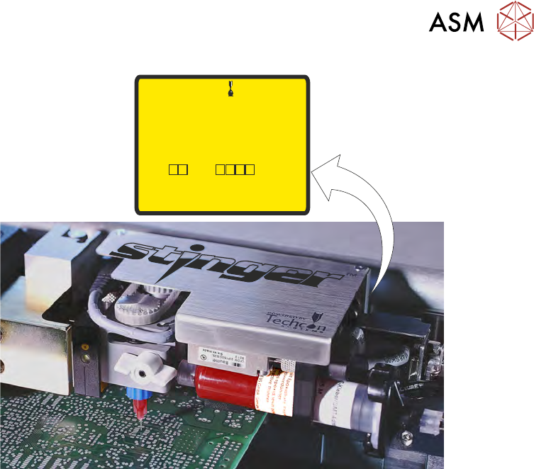
Stinger is a glue dot dispenser module attached to the camera carriage. After the product has been
printed, Stinger dispenses adhesive dots, from a syringe, in a pre-programmed pattern to the
product’s top surface. Adhesive is dispensed through a self-contained consumable auger unit; this
allows change over with no system cleaning.
A laser attached to the module is used as a depth gauge at the dispense sites and other locations;
each reading is used to check that the dispense gap is maintained, even where board warpage ex-
ists. If the product height is good, a glue dot is deposited at the location.
2.2.1.1 Purpose
The dispensed adhesive is used to hold larger mass components, which may, as a result of trans-
portation, or where under-components are used, move after placement.
1
2
3
4
5
6
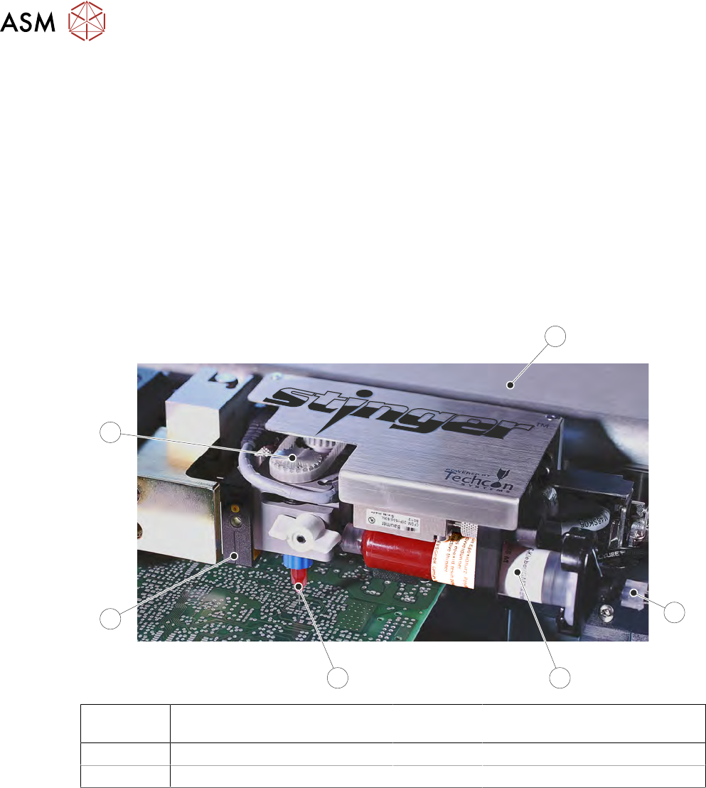
1 Camera Carriage 4 Nozzle and Auger Valve
Assembly
2 Air Input Connector 5 Laser Unit
3 10cc Syringe 6 Auger Pulley
2.2.1.2 Elements
The assembly comprises the following:
●
Syringe, nozzle and pneumatic connector
●
Consumable low-level sensor
●
Laser light source
●
Auger drive and Z axis motor assemblies
●
Electrical and pneumatic controls
●
Purge Station (optional)
2 STINGER, A GUIDE TO ADHESIVE DOT DISPENSING
2.2 INTRODUCTION
GUIDE TO ADHESIVE DOT DISPENSING STINGER 03/2021 11
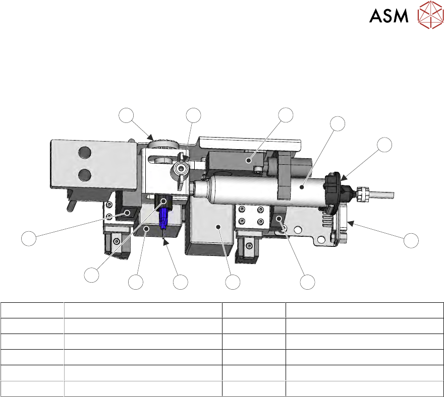
2.2.1.3 Syringe Assembly
The syringe attaches to an auger assembly at its outlet end and to a pneumatic supply at the other
end; the unit is supported in a ‘C’ shaped clamp. The auger, a ‘T’ shaped valve, is held in the dis-
penser with a plastic clamp screw; it engages with a motor driven pulley.
1
2
5
3
4
67
11
8
9
10
12
1 Level Sensor 7 Nozzle
2 Syringe 8 Auger Motor
3 Pneumatic Connector 9 Auger
4 Electrical Connector 10 Laser
5 ‘C’ Clamp 11 Auger Motor Pulley
6 Z Axis Motor 12 Auger Clamp Screw
A slightly positive air pressure is pulsed at the rear of the syringe to ensure the auger valve is not
starved of adhesive and a consistent supply is maintained. The pulses are programmed in software
to correspond with the auger feed movement phases of the dispense cycle.
2.2.1.4 Adhesive Delivery Mechanism
The delivery mechanism consists of an Archimedes screw fitted in the auger valve. A stepper mo-
tor and pulley assembly (not shown) rotate the screw in the auger valve. This action, combined with
the positive air feed at the rear of the syringe, ensure a consistent level of dispense when used in
the correct operating conditions (temperature/humidity). The auger is purged with adhesive after a
syringe has been replaced.
The drive rotates for a pre-programmed number of steps in the feed direction. The adhesive flows
out of the nozzle onto the product surface, forming a dot. At the end of each dispense, the motor
can be reversed, this allows the auger to draw adhesive back into the nozzle to avoid ‘stringing’.
The number of motor steps, speed, and direction are programmable parameters.