HS50的结构及原理.pdf - 第44页
2 Operational Safety Adjustment Instructions SIPLACE HS-50 2.3 Residual Voltages in the S ervo and Discharge Periods Edition 05/00 44 5HVLGXD O9 ROWDJHVLQWKH6HUY RDQG'LVFKDUJH 3HULRGV When the E MERG ENC…
Adjustment Instructions SIPLACE HS-50 2 Operational Safety
Edition 05/00 2.2 Safety Equipment
43
The following variants may be used:
Item no 00116820-01 SIPLACE guard for 1 location
Item no 00116821-01 SIPLACE guards for 6 - 10 locations
Item no 00116822-01 SIPLACE guards for 11 - 20 locations

2 Operational Safety Adjustment Instructions SIPLACE HS-50
2.3 Residual Voltages in the Servo and Discharge Periods Edition 05/00
44
5HVLGXDO9ROWDJHVLQWKH6HUY RDQG'LVFKDUJH
3HULRGV
When the EMERGENCY STOP button is pressed or the placement system is switched off, the
link voltages 200 V for the gantry axes and 100 V for the star - axes, will quickly discharge to safe
residual voltage levels.
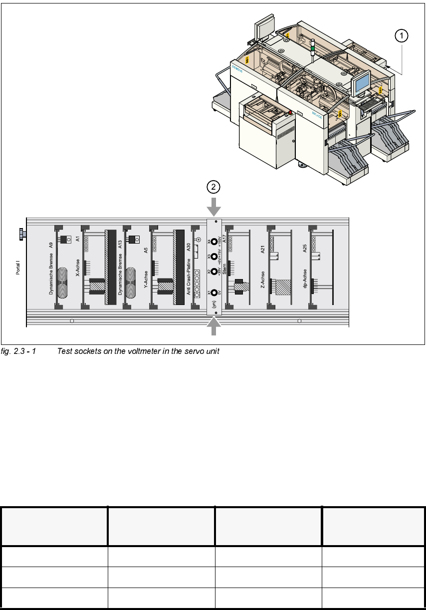
The voltages can be tapped off at test sockets X1 - X4 on the voltmeter unit in the servo unit.
DANGER
The placement system is powered with 3 x 204 VAC (US version) 3 x 230 VAC, 3 x 380 VAC,
3 x 400 VAC respectively 3 x 415 VAC ± 5 %, 50/60 Hz main power voltage. This means that
parts of the system carry potentially lethal voltages - even when the main switch is turned off.
Death, serious injury and considerable damage may result if these placement systems are han-
dled incorrectly.
Å Always follow the applicable accident prevention and DIN regulations. (Particularly EN 60204,
part 1).
Å The guard over the servo unit must ONLY be opened by appropriately qualified and trained
personnel.
Adjustment Instructions SIPLACE HS-50 2 Operational Safety
Edition 05/00 2.3 Residual Voltages in the Servo and Discharge Periods
45
.(<
(1) Location of the servo unit
(2) Voltmeter in the servo unit
5HVLGXDO9ROWDJHVDQG'LVFKDUJH3HULRGVDIWHU3UHVVLQJWKH(0(5*(1&<
6723%XWWRQ
7HVWVRFNHWV;;;
PHDVXUHGDW;*1'
9ROWDJHLQQRUPDOPRGH
5HVLGXDOYROWDJHDIWHU
(0(5*(1&<6723
'LVFKDUJHSHULRGV
X2 + 30 VDC + 30 VDC -
X3 + 100 VDC < 10 VDC 50 sec
X4 + 200 VDC < 10 VDC 7 sec