SIPLACE D4-D4i 工程师手册_EN.pdf - 第65页
Service Work 4.2.6 Replacing the Deflection Unit [00330938-0 2] Gantry Service Manual SIPLACE D4/D4i 65 4.2.6.3 4 . 2 . 6 . 3 R e m o v in g t h e d e f le c t io n u n it Removing the deflection unit ► Switch the machin…
Service Work
Gantry 4.2.6 Replacing the Deflection Unit [00330938-02]
64 Service Manual SIPLACE D4/D4i
4.2.5.4
4.2.5.4 Installing the tensioning keys
Installing the tensioning keys
4.2.5.5
4.2.5.5 Settings
Settings
4.2.6
4.2.6 Replacing the Deflection Unit [00330938-02]
Replacing the Deflection Unit [00330938-02]
4.2.6.1
4.2.6.1 Tools and Equipment
Tools and Equipment
▪ Set of DIN 911 Allen keys
▪ Belt tension measuring device TSM [00326015-01]
▪ "Measuring belt tensions" operating instructions
4.2.6.2
4.2.6.2 Parts
Parts
▪ Deflection unit X [00330938-02]
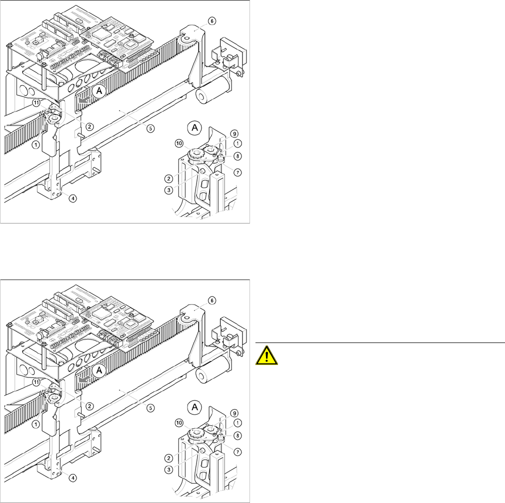
Replacing the tensioning keys
Installing the tensioning key, item 1 (synchronizing disk,
short)
► Place the tensioning key on the "short synchronizing
disk" (9).
► Fasten the tensioning key with the M4 x 5 hexagon
socket-head screw (8).
Installing the tensioning key, item 2 (synchronizing disk,
long)
► Use the Benzing U clip to fit the spacer bolt (7) onto
the new tensioning key.
► Place the tensioning key on the "long synchronizing
disk" (10).
► Use the size 8 Allen key to turn the synchronizing disk
slightly until the hexagon socket-head screw (3) can
be screwed in.
► Pretension the toothed belt by turning the hexagon
socket-head screw clockwise.
Replacing the tensioning keys
► Push the head mount towards the X-axis motor as far
as the stop on the elastomeric spring.
► Turn the hexagon socket-head screw to set the belt
tension to 53 Hz + 1/3 Hz.
CAUTION! Do not overstretch the toothed belt
when adjusting the belt tension.
► Secure the hexagon socket-head screw (3) with the
locknut (11).
Service Work
4.2.6 Replacing the Deflection Unit [00330938-02] Gantry
Service Manual SIPLACE D4/D4i 65
4.2.6.3
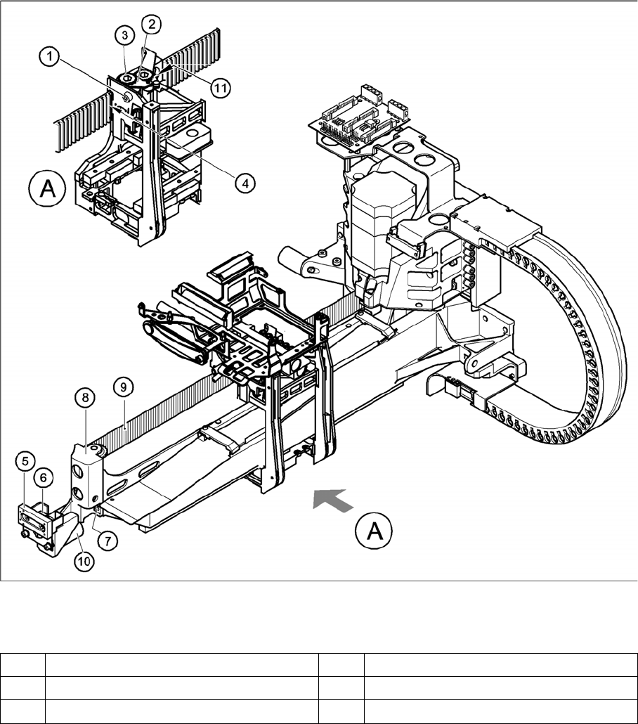
4.2.6.3 Removing the deflection unit
Removing the deflection unit
► Switch the machine off and secure it to prevent unauthorized reactivation, as described in section
4.3 from page 104 onwards.
► To relax the toothed belt (9), proceed as follows:
⇨ Loosen the locknut (11),
⇨ Turn the hexagon socket-head screw (1) counterclockwise.
► Remove the M4 x 35 hexagon socket-head screw (1).
► Pull the tensioning key (2) off the synchronizing disk (3).
► Pull the toothed belt (9) out through the opening in the tension jack (4).
► Unthread the toothed belt from the deflection unit (8).
► Loosen the two M3 x 8 hexagon socket-head screws (6) and remove the Y-brake "outside" (5).
► Loosen the two M6 x 10 hexagon socket-head screws (7) and remove the deflection unit ’X’ (8).
► Remove the elastomeric spring (10) from the deflection unit.
Replacing the deflection unit
Legend
1 M4 x 35 hexagon socket-head screw 7 2 x M6 x 10 hexagon socket-head screws
2 Tensioning keys 8 Deflection unit - X
3 Synchronizing disk, long 9 Synchroflex toothed belt
Service Work
Gantry 4.2.6 Replacing the Deflection Unit [00330938-02]
66 Service Manual SIPLACE D4/D4i
4.2.6.4
4.2.6.4 Installing the deflection unit ’X’
Installing the deflection unit ’X’
See also
4.2.6.3 Removing the deflection unit [ ➙ 65]
4.2.6.5 Settings [ ➙ 67]
4 Opening in tension jack for toothed belt 10 25 x 10.5 x 50 elastomeric spring
5 Y-axis brake, external 11 Locknut
6 2 x M3 x 8 hexagon socket-head screws
Replacing the deflection unit
► Fit the elastomeric spring (10) on the new deflection
unit (8).
► Fix the deflection unit (8) to the gantry, with the two
M6 x 10 hexagon socket-head screws (7).
► Align the brake "outside" (5) so that it is parallel with
the braking surface and fix it to the deflection unit (8)
with the two M3 x 8 hexagon socket-head screws.
► Run the toothed belt (9) around the synchronizing
disk of the deflection unit (8).
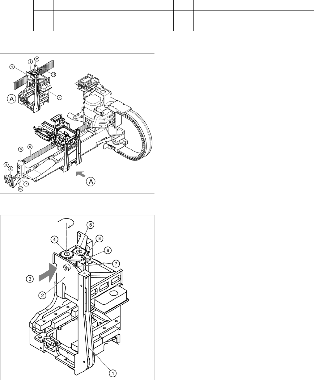
Fitting the toothed belt on the tension jack
Legend
1. Head mount
2. Tension jack for the toothed belt
3. Opening for threading the toothed belt
4. Synchronizing disk, long
5. Tensioning keys
6. Spacer bolt with M4 threaded hole
7. M4 x 35 hexagon socket-head screw for tensioning
the toothed belt
8. Locknut
► Insert the toothed belt through the opening (3) in the
tension jack (2) until the toothed belt is run approx.
270° around the "long synchronizing disk" (4).
► Place the tensioning key (5) onto the synchronizing
disk (4).
► Use a size 8 Allen key to turn the synchronizing disk
(4) clockwise.
► Turn the hexagon socket-head screw (7) into the drill-
ing provided for the spacer bolt (6) and pretension the
X toothed belt.