00192792-02.pdf - 第86页
2 Retrofitting Instructions: M atrix Tray Changer MTC on S-25 HM (Option) SIPLACE 80 S-25 HM 2.8 Installing t he MTC 01/01 Issue 86 CAUTION before CONNE CTION the MTC For opera tion at 1 10V~, the option for USA "1 …
SIPLACE 80 S-25 HM 2 Retrofitting Instructions: Matrix Tray Changer MTC on S-25 HM (Option)
01/01 Issue 2.8 Installing the MTC
85
.H\
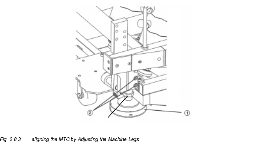
1. Machine leg
2. Clamping screws
Å At a conveyor height of 830 mm: On the bottom of the MTC machine frame, disassemble the
U-shaped cover plate so that the two clamping screws (see Fig. 2.8.3 -> Pos. 2) are accessible.
To accomplish this, loosen the 6 screws on the cover plate (size 3 Allen wrench).
Å Then align the MCT using fork wrenches, width across the flats 30 - 36, to adjust the machine
legs such that the air bubble of the fisheye is exactly in the middle of the adjustment gauge.
This is described in detail in the MTC User Manual.
Å During this process it is possible that you will ultimately have to correct the height of the MTC
again so that the red ring (see Fig. 2.8.2) is again just barely visible when the air bubble is in
the middle.
Å Lock the machine legs in this position with the clamping screws (see Fig. 2.8.3 -> Pos. 2):
socket hex head cap screws M8 (size 6).
Å Remove the setting gauge and return it to the enclosure in tower 1 of the MTC.
Å Re-install the cover plate of the MTC (6 screws, size 3 Allen wrench).
Width across the flat = 13
2 Retrofitting Instructions: Matrix Tray Changer MTC on S-25 HM (Option) SIPLACE 80 S-25 HM
2.8 Installing the MTC 01/01 Issue
86
CAUTION before CONNECTION the MTC
For operation at 110V~, the option for USA "110 V~ voltage module MTC" must be retrofitted.
For Japan the "External power supply MTC" must be retrofitted (see retrofit kits, in Section 2.5).
Å Connect the power supply and interface cable for the MTC and the component table (where
applicable, an existing second MTC including component table). The safety circuit of the MTC
and the component table is closed via the interface cable.
$VVHPEOLQJWKH0DF KLQH
Å In the case of machines WITH opening for MTC (up to approximately serial no. 450):
Hook the NEW "Component reject box MTC" onto the machine frame next to the MTC (see
Fig. 2.7.17).
If a second MTC has been retrofitted, do this at the other location too.
Å In the case of machines WITHOUT opening for MTC (up to approximately serial. no 449):
Place the new "component reject box table", Item no.: 00355146-01 (from the MTC retrofit kit),
on the component table immediately to the right of the MTC.
NOTICE:
It will be necessary to configure the type of reject box later in SITEST (see: Section 2.8.5).
Å If a movable component changeover table has to be connected at a location with no MTC, turn
the compressed air back ON at the main valve of the machine’s compressed air unit now. Turn
the machine back ON.
Connect the movable component changeover table as described in the User Manual.
Å Conduct a visual inspection to make certain that all empty-tape ends are correctly guided down
in the empty-tape duct.
Å Close all of the safety doors/covers and the machine’s safety hood.
&RQILJXUDWLRQRIWKH07&
The software automatically recognizes the option MTC if both the MTC and the component table
were completely connected before the machine was turned ON (interface and power supply).
If this procedure was not followed, the option MTC can be activated later in SITEST:
Å In the basic menu of SITEST select -> Location integration (button).

SIPLACE 80 S-25 HM 2 Retrofitting Instructions: Matrix Tray Changer MTC on S-25 HM (Option)
01/01 Issue 2.8 Installing the MTC
87
6,7(67&RQILJXULQJDQG0HD VXULQJWKH1R]]OH&KD QJHU07&
DANGER:
It is a fundamental rule that the SITEST program is only to be started by personnel trained in the
application by Siemens and therefore authorized to do so.
Aside from generally higher risk of accident, additional higher risk of accident exists when the
SITEST program is used, due to the blades of the cutter.
The cutter and the empty-tape duct must always be completely assembled.
The MTC and the component changeover table must always be correctly connected.
Once the nozzle changer has been completely installed, it must be configured and measured:
– All placement heads and cameras must already have been calibrated beforehand (see SIT-
EST User Manual).
Carry out the following procedure for the nozzle changer MTC recently installed.
NOTE
The configuration and calibration must be conducted for the gantry at which the MCT is installed.
This may be either at location 1 (gantry 1) or location 3 (gantry 2) or at both locations.
The procedure for gantry 1 with configured 6-segment revolver head is described below. The dif-
ference between RV6- and RV12-head and magazine allocation will be discussed during the fol-
lowing process - at the necessary point.
The
)LJ
shows the SITEST menu for the nozzle changer magazine configuration for the
59
nozzle changer MTC.
Å Change to the SITEST program.
Å The basis view will be displayed.
Å Starting at the main view, select -> Settings -> Machine configuration -> "Gantry 1" or "Gantry
2", depending on the location at which the MTC was installed.
The following screen is displayed: