00195440-05-SG_D-Series_FSE-EN.pdf - 第263页
15 SIPLACE Measuring Tools 15.1.1 Scope of Delivery 15.2 SIPLACE Diagnosis Adapter A364 [03 051220-0 1] Student Guide SIPLACE D-Series (FSE) 263 15.1.1 1 5 . 1 . 1 S c o p e o f D e liv e r y Scope of Delivery The SIPLAC…
15 SIPLACE Measuring Tools
15.1 SIPLACE Axis Tester (SAT) [03002801-01]
262 Student Guide SIPLACE D-Series (FSE)
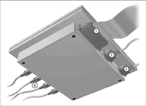
Axis tester - view from below
Legend
1. Connection for flat ribbon cable:
– At the axis tester end:
– 37 pin Sub-D connector
– At the axis control end:
– 37 pin Sub-D connector for the S-20/23/25/F4/F5 and HS-50 machines, with the axis control
units A361 or A362
– 25 pin Sub-D connector for the S-15/F3, G machines and the wafflepack changer, with the axis
control unit A360
An adapter is attached to the flat ribbon cable for connection of the 25 pin axis control. The op-
erating voltages of +5 V- ±5 % and ±15 V- ±5 % are fed via the 37 pin flat ribbon cable from the
axis control unit to the axis tester.
2. 9 pin Sub-D connector for CAN Bus cable e.g. for connection of CAN Bus controlled boards in the
machine – currently not used (transmission rate 128 kBaud to 1 MBaud, impedance 120 Ohm)
3. 9 pin Sub-D connector for the serial interface cable (V24) needed for software downloads, e.g. for
connection of an external PC (max. transmission rate up to 188 kBaud)
4. Four BNC sockets, connection impedance 50 Ohm. Socket assignment can be programmed. The
following signals can be assigned:
– Track signal A or B TTL level, max. 5 V
– Zero pulse TTL level tmin = 1 µsec
– End position signal TTL level tmin > 10 msec
– Trigger TTL level tmin > 10 msec
– Count error TTL level, trigger signal from count error sensor of oscilloscope
– Vtarget ±10 V, analog signal, Ri = 10 kOhm
– Force ±10 V analog signal, Ri = 10 kOhm
– VREG (resulting current) ±10 V analog signal, Ri = 10 kOhm
– Position deviation ±10 V analog signal; signal generated internally in axis tester.
15 SIPLACE Measuring Tools
15.1.1 Scope of Delivery 15.2 SIPLACE Diagnosis Adapter A364 [03051220-01]
Student Guide SIPLACE D-Series (FSE) 263
15.1.1
15.1.1 Scope of Delivery
Scope of Delivery
The SIPLACE axis tester package [03002801-01] contains the following components:
▪ SIPLACE axis tester [03000761-01]
▪ Test cable A361 ... A363 (length 150 cm) with 37 pin connector and 37 pin socket for connection of
axis control units from S2x, F4/F5 and HS machines [03002803-01]
▪ CAN Bus cable [00349679-03]
▪ RS232-C cable [03002804-01]
▪ Manual for axis tester [00193370-01]
15.2
15.2 SIPLACE Diagnosis Adapter A364 [03051220-01]
SIPLACE Diagnosis Adapter A364 [03051220-01]
Application:
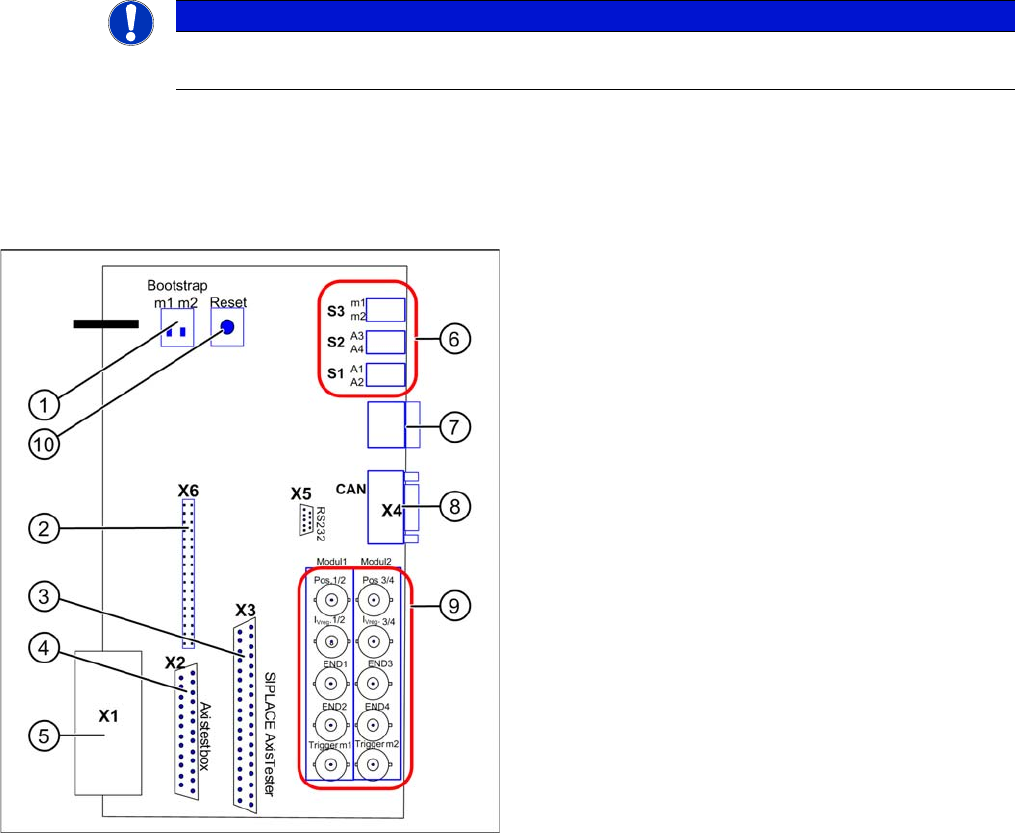
The adapter card is used to check the A364 axis card dynamics.
The A364 axis card is equipped with two processors (module 1 and module 2) i.e. one processor controls
two axes.
NOTICE
This adapter is designed for all machines with A364 and as an adapter for the CAN test box
with force measuring tool.
Adapter card for A364
Legend
Module 1: Axis 1/2
Module 2: Axis 3/4
1. Bootstrap mode: m1 = module1 / m2 = module2
2. Diagnosis – connector X6
3. Connection X3 SIPLACE AxisTester
4. Connection X2 Axis test box
5. Connection X1 to A364
6. Switches:
7. Diagnosis – 7 segment display
8. CAN bus connector (Sub-D)
9. BNC sockets:
10. Reset both processors
15 SIPLACE Measuring Tools
15.3 Adjustment Aid for Changeover Table [00120040-01] 15.1.1 Scope of Delivery
264 Student Guide SIPLACE D-Series (FSE)
15.3
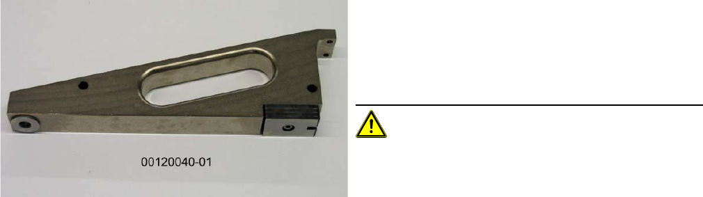
15.3 Adjustment Aid for Changeover Table [00120040-01]
Adjustment Aid for Changeover Table [00120040-01]
This setting gauge is not provided in the SIPLACE Pro computer delivery package and needs to be or-
dered separately for a new line.
▪ Application:
The adjustment aid is needed for calibration of the
changeover table.
It is only needed (or can only be used) for SIPLACE
S tables.
CAUTION! Never use more than one adjust-
ment aid for pickup position calibration on one changeo-
ver table.Exception: You may occasionally need to use
another adjustment aid for a different side of the machine
or line.