Oxford-100-Cryo-DRIE-SOP-in-PDF-Format.pdf - 第3页
Oxford 100 Cryo DRIE SOP Page 3 of 10 Revision 1-060810 Figure 2, Load Lock 6.6 Turn on the Chiller 6.6.1 Go into the chase behind the Oxford 100. 6.6.2 Turn the power switch to start on the chiller. See Figure 1, Chille…
Oxford 100 Cryo DRIE SOP Page 2 of 10
Revision 1-060810
Power
Switch
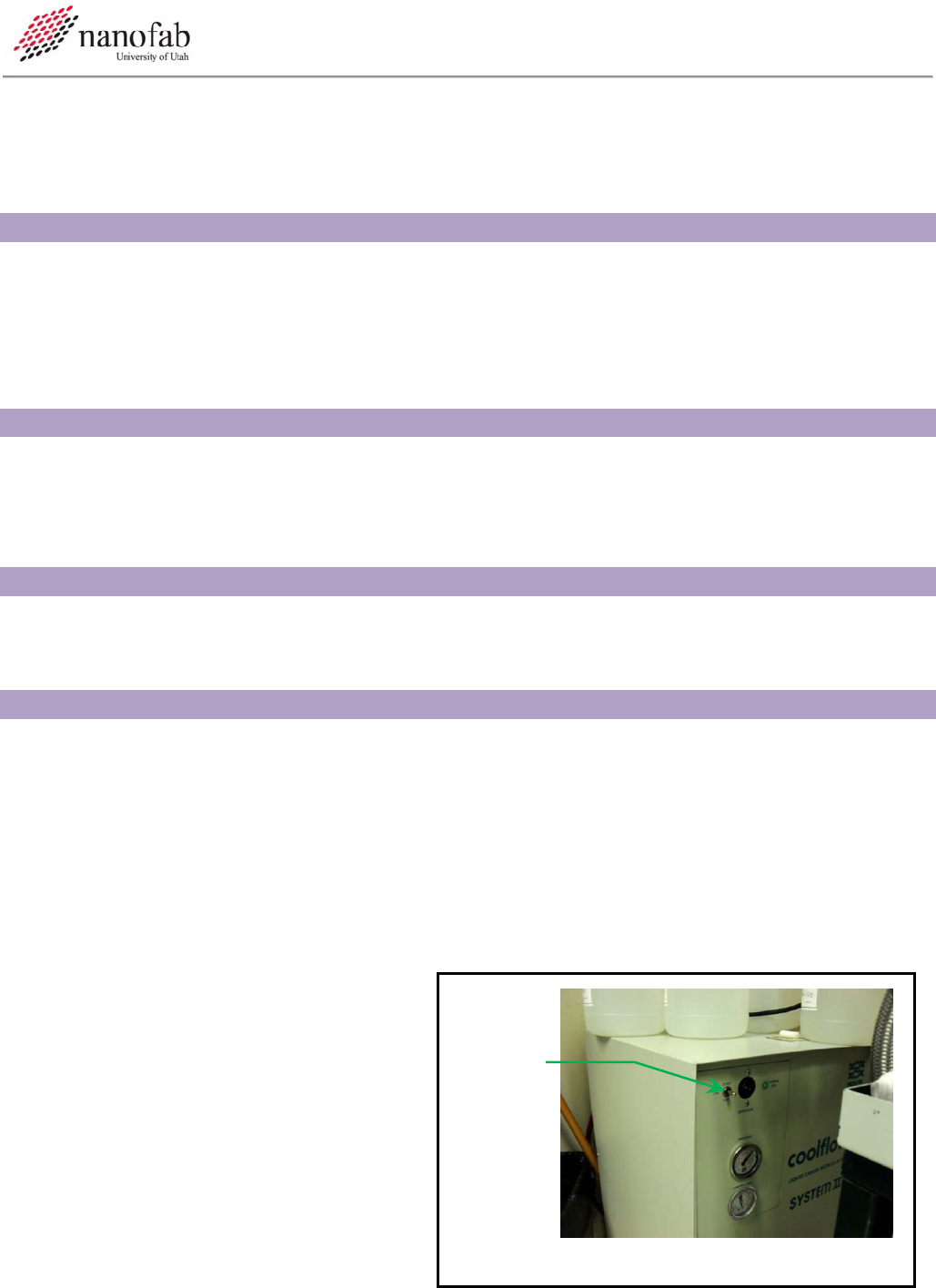
Figure 1, Chiller
Table 1, Cleaning Recipe Parameters ......................................................................................................................... 7
Table 2, Cryo DRIE Parameters ................................................................................................................................ 10
3. Reference Documents
3.1 Referenced within this Document
3.1.1 Ecosys Burn Box SOP
3.2 External Documents
3.2.1 None
4. Equipment and/or Materials
4.1 Wafer/Sample
4.2 Oxford 100
4.3 Liquid Nitrogen
5. Safety
5.1 Follow all Nanofab safety procedures.
5.2 Include all other safety precautions necessary for these procedures.
6. Setup Procedures
6.1 Record Information in Log Book
6.1.1 Record all processing and characterization information in log book.
6.2 Turn on Burn Box
6.2.1 Follow the procedure in the Ecosys Burn Box SOP to turn on the burn box.
6.3 Clean the Chamber
6.3.1 Run the cleaning recipe as described in for 25 minutes for every hour of Bosch use. See
Section 9.1 Chamber Cleaning.
6.4 Mask Wafer
6.4.1 For etch depths less than 20 um,
S1813 spun at 3000 RPM can be
used. For depths greater than 20 um,
it is highly suggested that you use a
thicker resist. The etch selectivity of
Si:S1813 is about 10:1.
6.5 Turn on the Liquid Nitrogen
6.5.1 Open the liquid nitrogen valve.
Oxford 100 Cryo DRIE SOP Page 3 of 10
Revision 1-060810
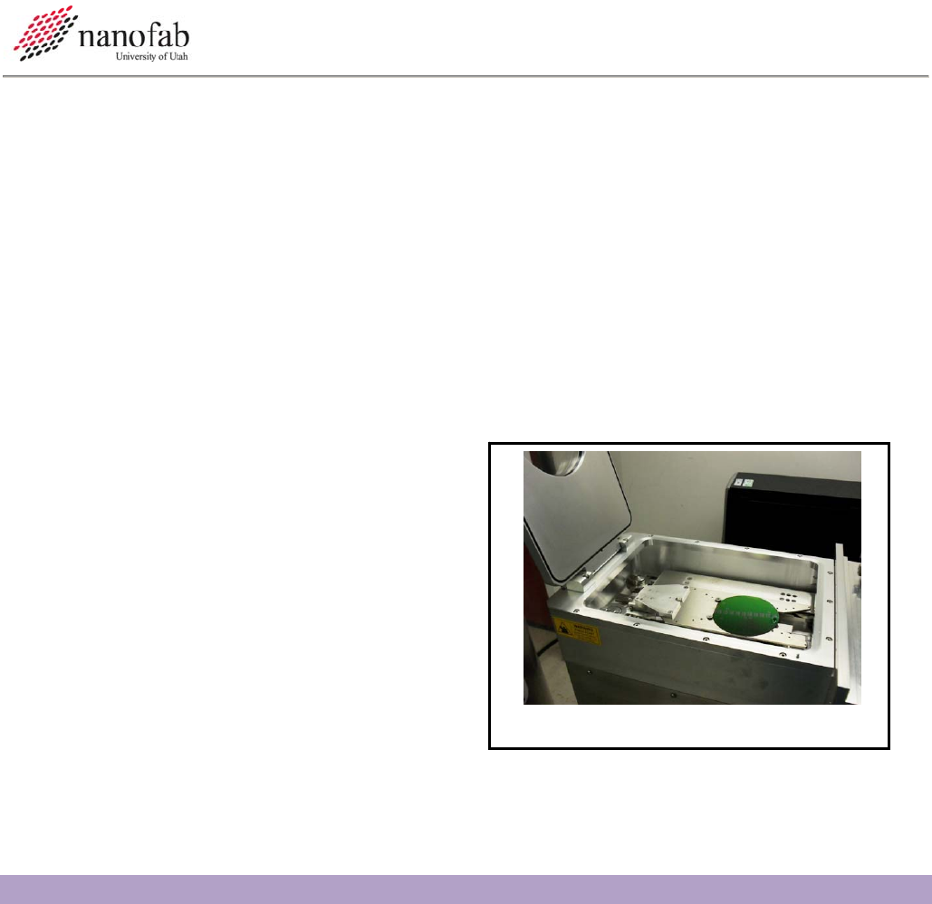
Figure 2, Load Lock
6.6 Turn on the Chiller
6.6.1 Go into the chase behind the Oxford 100.
6.6.2 Turn the power switch to start on the chiller. See Figure 1, Chiller.
6.7 Vent load lock.
6.7.1 Click on system icon. See Figure 3, Pump Controls Page.
6.7.2 Click on pump page.
6.7.3 Press stop button corresponding to the load lock mechanical pump. See Figure 3, Pump
Controls Page
6.7.4 Press vent button. See Figure 3.
6.7.5 Wait for load lock to vent. The pressure will read above 600 Torr and the time will be 0.
6.8 Load Wafer
6.8.1 Open load lock lid.
6.8.2 Press stop button.
6.8.3 Place wafer in load lock against the two
pins on the transfer arm with the wafer
facing the two pins. The wafer should
touch the two pins. See Figure 2, Load
Lock.
6.9 Pump Down Load Lock
6.9.1 Close load lock lid.
6.9.2 Select the evacuate button. See Figure 3.
6.9.3 Enter an ID name or number for your wafer.
6.9.4 Wait for the load lock to pump down (~1 min).
7. Cryo Etching Procedure
NOTE: This recipe can be used to etch smooth shallow trenches in 100 mm wafers. It is strongly
advised that you do a test run on a practice wafer before working with your device wafer.
7.1 Transfer Wafer to Etch Chamber
7.1.1 Click on the icon for the etch chamber. See Figure 3.
7.1.2 Click on the icon for the load lock chamber.
7.1.3 Click on the etch chamber icon.
Oxford 100 Cryo DRIE SOP Page 4 of 10
Revision 1-060810
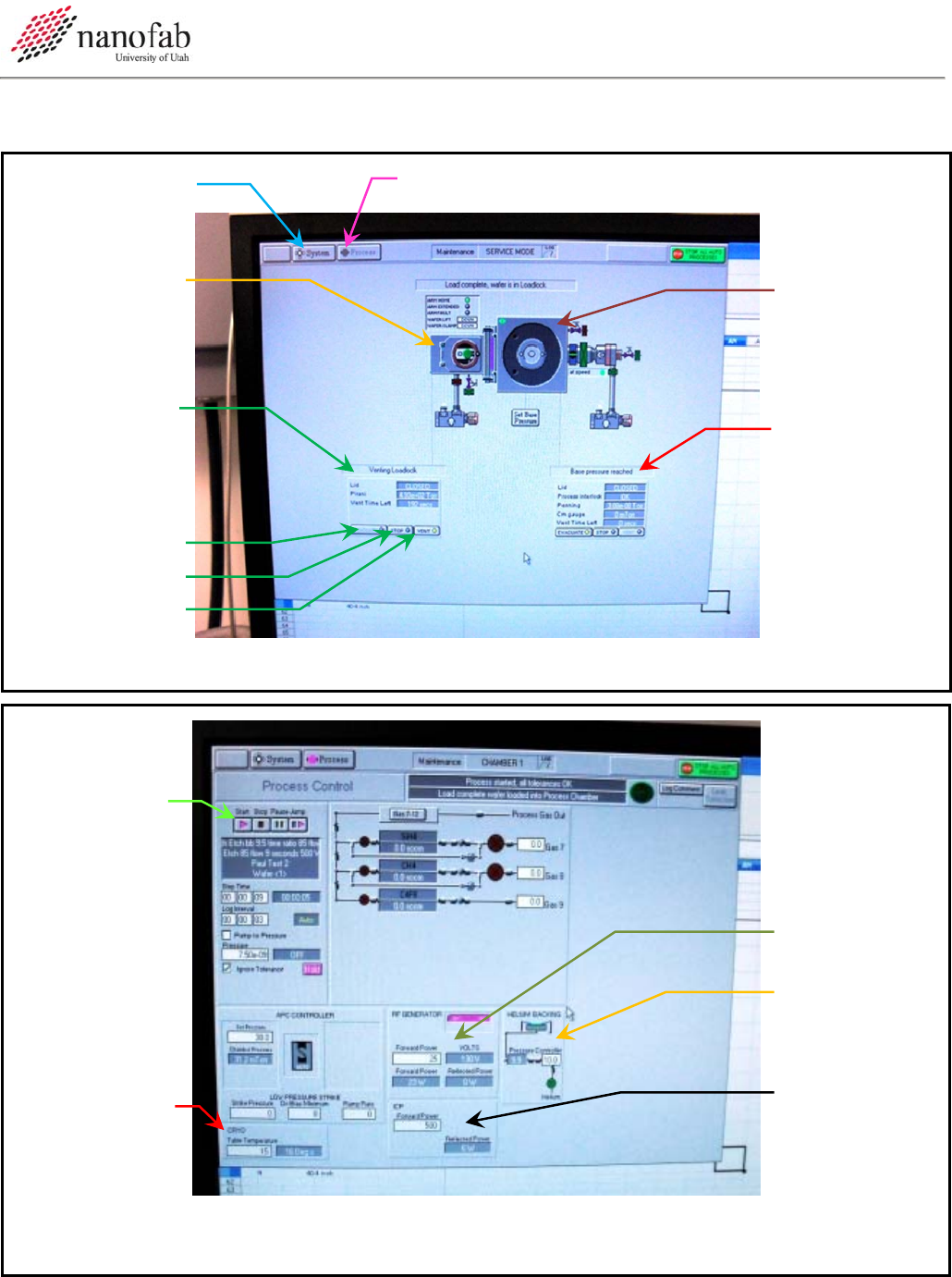
System
Button
Process Buttton
Load Lock
Controls
Evacuate
Stop
Vent
Main
Chamber
Controls Do
Not Touch
Load Lock
Icon
Main
Chamber
Icon
Figure 3, Pump Controls Page
Start Button
RF Power
He Backing
Pressure
ICP Power
Tem
p
erature
Figure 4, Process Controls Page