Oxford-100-Cryo-DRIE-SOP-in-PDF-Format.pdf - 第4页
Oxford 100 Cryo DRIE SOP Page 4 of 10 Revision 1-060810 System Button Process Buttton Load Lock Controls Evacuate Stop Vent Main Chamber Controls Do Not Touch Load Lock Icon Main Chamber Icon Figure 3, Pump Controls Pag …
Oxford 100 Cryo DRIE SOP Page 3 of 10
Revision 1-060810
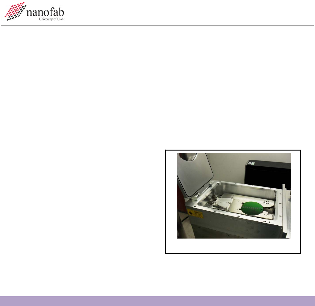
Figure 2, Load Lock
6.6 Turn on the Chiller
6.6.1 Go into the chase behind the Oxford 100.
6.6.2 Turn the power switch to start on the chiller. See Figure 1, Chiller.
6.7 Vent load lock.
6.7.1 Click on system icon. See Figure 3, Pump Controls Page.
6.7.2 Click on pump page.
6.7.3 Press stop button corresponding to the load lock mechanical pump. See Figure 3, Pump
Controls Page
6.7.4 Press vent button. See Figure 3.
6.7.5 Wait for load lock to vent. The pressure will read above 600 Torr and the time will be 0.
6.8 Load Wafer
6.8.1 Open load lock lid.
6.8.2 Press stop button.
6.8.3 Place wafer in load lock against the two
pins on the transfer arm with the wafer
facing the two pins. The wafer should
touch the two pins. See Figure 2, Load
Lock.
6.9 Pump Down Load Lock
6.9.1 Close load lock lid.
6.9.2 Select the evacuate button. See Figure 3.
6.9.3 Enter an ID name or number for your wafer.
6.9.4 Wait for the load lock to pump down (~1 min).
7. Cryo Etching Procedure
NOTE: This recipe can be used to etch smooth shallow trenches in 100 mm wafers. It is strongly
advised that you do a test run on a practice wafer before working with your device wafer.
7.1 Transfer Wafer to Etch Chamber
7.1.1 Click on the icon for the etch chamber. See Figure 3.
7.1.2 Click on the icon for the load lock chamber.
7.1.3 Click on the etch chamber icon.
Oxford 100 Cryo DRIE SOP Page 4 of 10
Revision 1-060810
System
Button
Process Buttton
Load Lock
Controls
Evacuate
Stop
Vent
Main
Chamber
Controls Do
Not Touch
Load Lock
Icon
Main
Chamber
Icon
Figure 3, Pump Controls Page
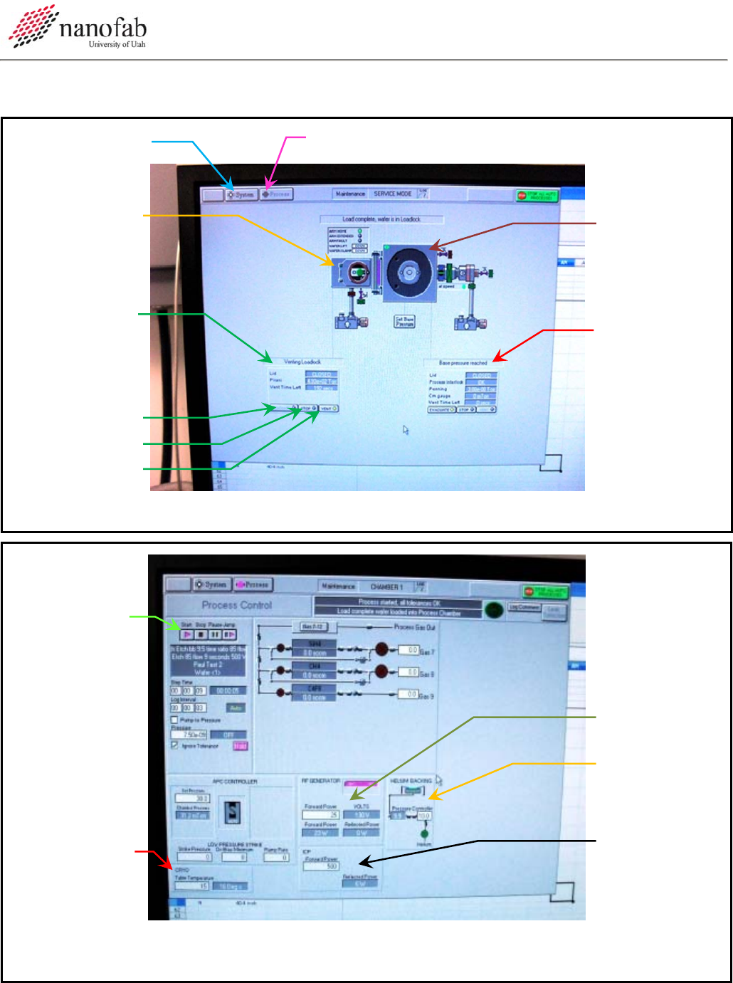
Start Button
RF Power
He Backing
Pressure
ICP Power
Tem
p
erature
Figure 4, Process Controls Page

Oxford 100 Cryo DRIE SOP Page 5 of 10
Revision 1-060810
7.2 Etching Si with a Photoresist Mask
7.2.1 Click Process button. See Figure 3, Pump Controls Page.
7.2.2 Select Chamber 1.
7.2.3 Verify that the “ignore tolerances” box is checked.
7.2.4 The temperature should be -120 C. See Figure 4, Process Controls Page.
7.2.5 Allow the chamber to pump down to ~1x10^-6 T (approx. 15 min).
7.2.6 Set the run time to 20 min.
7.2.7 Set the He backing pressure to 10mT.
7.2.8 Press the Start button. See Figure 4.
7.2.9 Allow He to flow for 3 min.
7.2.10 This should give a chamber pressure of 1-5x10^-5T.
7.2.11 Set the SF6 to 34.5sccm and the O2 to 5.5sccm.
7.2.12 Press the Start button.
7.2.13 The pressure should now be 3-6mT.
7.2.14 The pressure set point should be 0mT.
7.2.15 Set your desired etch time.
7.2.16 Set the RF power to 35W and the ICP power to 500W.
7.2.17 Click the Start button to begin your process.
7.2.18 Once the plasma ignites, immediately change the RF power to 5W.
7.2.19 Click Start button.
7.2.20 If plasma does not strike, stop the process and repeat steps with a higher striking RF power.
7.3 Control the Etch Profile
7.3.1 The etch profile can be controlled by adjusting the SF6 flow rate in the above recipe.
7.3.2 Increasing the SF6 will create a negative profile while doing the opposite creates a positive
profile. See Figure 5.