205020 OTS Standalone Manual.pdf - 第14页
OVER THE TO P SNUGGER (OTS) OVER VIEW 1.2 Over the T op Snuggers (OTS) Manual Chapter Issue 3 Aug 14 The OTS Clamps Figure 1- 1 Rear OTS Rai l Figure 1-2 Snugger Ass embly Brake Cy l inders ( 16 ) Snugger Guide ( 2 ) Snu…
OVER THE TOP SNUGGER (OTS)
OVERVIEW
Chapter Issue 3 Aug 14 Over the Top Snuggers (OTS) Manual 1.1
CHAPTER 1 OVER THE TOP SNUGGER (OTS)
OVERVIEW
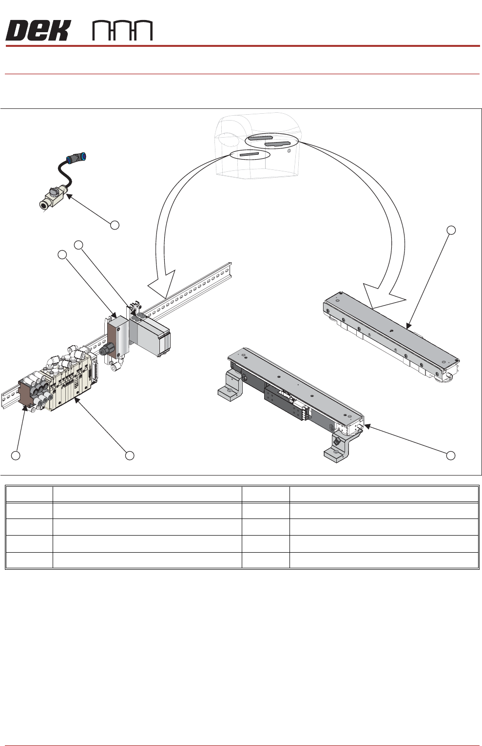
NOTE
The items shown above are representative and are not shown in their true
orientation or location within the printer.
Item Description Item Description
1 Rear Rail OTS Assembly 5 Vacuum Ejector
2 Front Rail OTS Assembly 6 ITV Valves
3 Pneumatic Valve Manifold 7 Isolator Switch Valve
4 Pneumatic Regulators
5
6
7
34
2
1
OVER THE TOP SNUGGER (OTS)
OVERVIEW
1.2 Over the Top Snuggers (OTS) Manual Chapter Issue 3 Aug 14
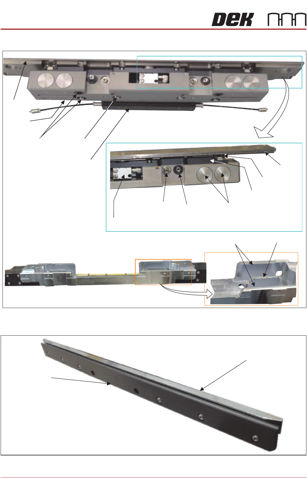
The OTS Clamps
Figure 1-1 Rear OTS Rail
Figure 1-2 Snugger Assembly
Brake Cylinders (16)
Snugger Guide (2)
Snugger Actuator (2)
Forward/Back Cylinder
(Top clamp movement)
Top Clamp Plate
Linear Bearing (2)
Bearing Support Plate
Brake Flanges (2)
Brake Surface
(inner wall)
Machined Body
Lift Cylinder (2)
Manifold
Mid Plate
Lift Guides (4)
Swivel
Plate
Cover
Top Clamp Plate
and Mid Plate Assembly
Snug Plate
Board Support

OVER THE TOP SNUGGER (OTS)
OVERVIEW
Chapter Issue 3 Aug 14 Over the Top Snuggers (OTS) Manual 1.3
Each OTS rail consists of:
• Board Support and Snug Plate (fixed on the front rail)
• Mid Plate housed in the Machined Body it has a pneumatic manifold
located at the rear of the assembly.
• Over the Top Clamp, comprising; the Swivel Plate the Bearing Support
Plate and the Top Clamp Plate
• A Pneumatic Manifold
• Magnetic Tooling Pins
Board Support and
Snug Plates
The board support, supports the product while it is in the tooling area of the
machine. The snug plate moves in and out to snug the product; this movement
is provided by the snugger actuators and guides in the mid plate assembly. If a
product is a shape that does not have parallel sides the snug plate pivots to
accommodate it. On the front rail this plate is fixed and does not move in the Y
axis.
Mid Plate Sixteen brakes hold the mid plate in place during printing; they brake against
the flanges and the side wall of the machined body. Print pressure up to 20Kg
in can take place. To release the brakes, a vacuum ejector valve switches on;
this pulls the brakes away.
Over the Top Clamp This assembly comprises three plates: Swivel, Bearing Support and Top Clamp.
The swivel plate is mounted on the bearing support plate which has a central
bearing and linear guides at both sides. If a product is a shape which does not
have parallel sides, the clamps can pivot to accommodate the shape and align
with the snugger. On the rear clamp only, the top clamp plate slides over the
top of the product to give top clamping.
Modes of operation can be programmed via the software. The parameter, OTS
Retain Mode, if enabled, allows the board to be held during the unclamping
phase of the cycle (see Sequences later in this manual.) If disabled, the clamp
is retracted preventing the possibility of smudging the print.
A forward/back cylinder mounted in the centre front of the block is used to move
the over top clamp forward or backward. The combination of up or down and
forward and backward movements allows the over the top clamp to be moved.
This either clamps the product, or it comes to rest at the same height as the
product, where it is positioned behind the snug plate at the rear of the assembly.
Manifold The manifold delivers pneumatic air pressure through ‘O’ ring sealed ports to
the various actuators which drive the OTS movements.
NOTE
Any attempt to disassemble parts invalidates all warranty agreements.
Modules must be serviced by a suitably qualified ASM trained engineer.