00198371-01_UM_SWS-EN.pdf - 第109页
User manual SIPLACE Wafer System (SWS) 6 Options Edition 04/2018 6.2 Optional components 109 6.2.3 Barcode scanner The barcode scanner on the SWS reads the barc ode on the wafer frame. The barcode sca nner can be fitted …
6 Options User manual SIPLACE Wafer System (SWS)
6.2 Optional components Edition 04/2018
108
6.2.2 Die attach unit
6
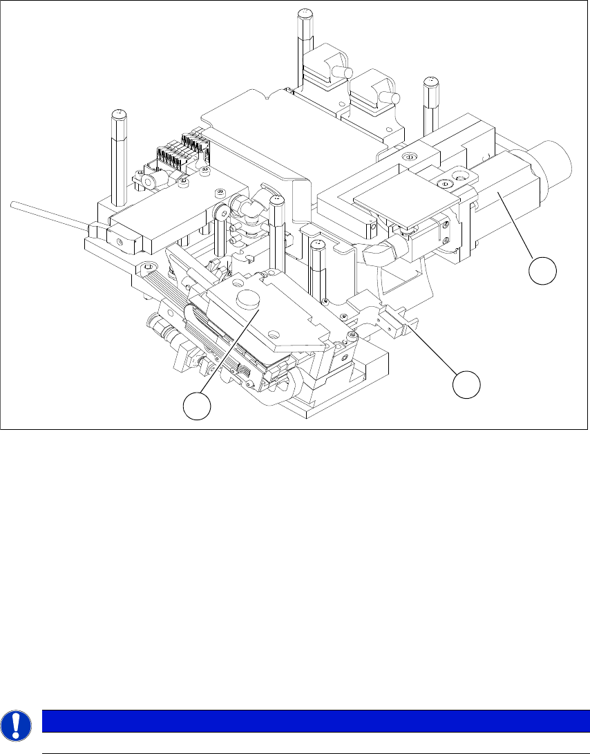
Fig. 6.2 - 2 Die attach unit
(1) Drive motor for rotating the die attach axis
(2) Driver for X axis transfer
(3) Motor transfer X axis
The die attach unit is needed for die attach mode.
The flip unit transfers the die to the die attach unit. The die is then rotated accordingly there and
made available for pickup. The die is therefore made available to the placement head in the same
top/bottom orientation as it was on the wafer and is placed in this position.
In die attach mode, only segment 1 of the flip unit functions. The flip unit takes up the next die,
while the current die is being picked up by the placement head from the die attach unit.
6
PLEASE NOTE
The die attach unit can NOT be used together with the LDU SWS.
1
2
3
User manual SIPLACE Wafer System (SWS) 6 Options
Edition 04/2018 6.2 Optional components
109
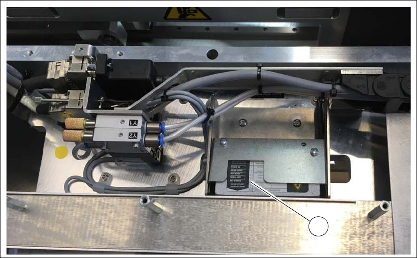
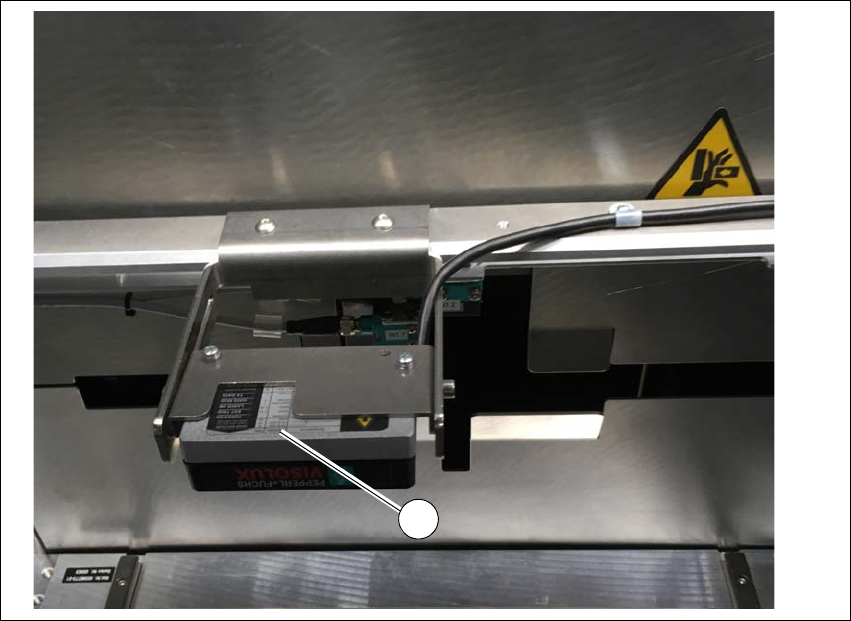
6.2.3 Barcode scanner
The barcode scanner on the SWS reads the barcode on the wafer frame. The barcode scanner
can be fitted in two positions:
– On the magazine lift
– On the gripper
6
Fig. 6.2 - 3 Barcode scanner - example of installation on the gripper
(1) Barcode scanner
1
6 Options User manual SIPLACE Wafer System (SWS)
6.2 Optional components Edition 04/2018
110
6
Fig. 6.2 - 4 Barcode scanner - example of installation on the magazine lift
(1) Barcode scanner
1