Nordson_EFD_Series_400_Instructions.pdf - 第4页
Series 400 Autovalve | Instructions / Parts Lists 4 www.nordsonefd.com info@nordsonefd.com +1-401-431-7000 Sales and service of Nordson EFD dispensing systems are available worldwide. Maintenance Disassembly and Cleaning…

Series 400 Autovalve | Instructions / Parts Lists
3www.nordsonefd.com info@nordsonefd.com +1-401-431-7000 Sales and service of Nordson EFD dispensing systems are available worldwide.
Operation
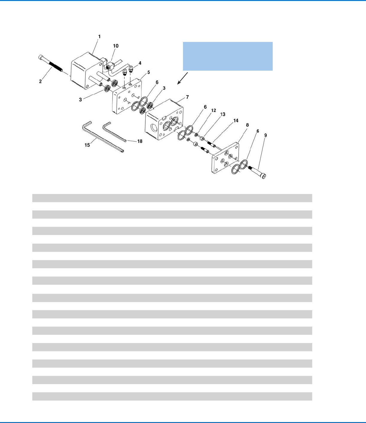
The ON-OFF operation of the valve is controlled by movement of the piston inside the air cylinder (1). In the OFF position, the
piston advances and the front seal (13) seats into the seat plate (8).
In the ON position, the piston and seals retract from the seat plate (8), which allows A & B fluids to pass through the manifold.
A disposable Series 160 mixer can be attached to the manifold. If the operating pressure exceeds 10bar (150psi), we
recommend a metal jacket be used over the plastic mix tube.
NOTE: For all reference numbers in parenthesis, see pages 5–9.
Your 400 AUTOVALVE in general...
• Designed to dispense two-component adhesives and sealants
• Dispenses low or high viscosity urethanes, epoxies and silicones
• Can be mounted for beads or timed shots; optional handle is available for hand held applications
• Provides an ON-OFF function. The metering of the adhesives in the proper ratio of A:B is controlled by the metering
pumps.
Installation
Connect Supply Lines
The A & B fluid hoses are connected to the side of the valve body (7), between the valve and the pumps, and should be as
short as possible. It is a good practice to install check valves in the hoses just before the valve. Optional fitting with check
valve is listed on page11.
For stationary mount, the air lines will be connected to the side of the air cylinder (1). Air to the back of the cylinder to close
and air to the front to open. If the optional handle is used, air is connected to the barbed fitting (105) on the side of the
handle.
The air line should have minimum pressure of 5.5bar (80psi).
Startup
1. With the hand-held model, start metering pumps and purge the air out of the A & B hoses and Autovalve. After the A and
B fluids come out of the manifold, attach a mixer to the manifold and hold the valve upside down with the mixer pointing
up. Dispensing A & B will purge the last pockets of air in the valve body.
A stationary mount or gantry installation requires a swivel mounting bracket. To complete purging, turn the valve with the
mixer pointing up and dispense A & B.
2. Take a ratio check by weight of A:B after the manifold. The Autovalve does No Metering. The Volume Ratio of A:B is
controlled by the metering pumps. However, between the metering pumps and the Autovalve are hoses. These hoses
will expand under pressure and cause lead-lag problems. Lead-lag refers to the uneven starting of the A fluid before the
B fluid. Nordson EFD offers 1:1 and wide ratio manifolds to reduce this problem. The selection of the correct manifold
depends on both the volume and viscosity ratio of A and B.
Consult EFD Technical Services for details at 800-556-3484.
Series 400 Autovalve | Instructions / Parts Lists
4 www.nordsonefd.com info@nordsonefd.com +1-401-431-7000 Sales and service of Nordson EFD dispensing systems are available worldwide.
Maintenance
Disassembly and Cleaning
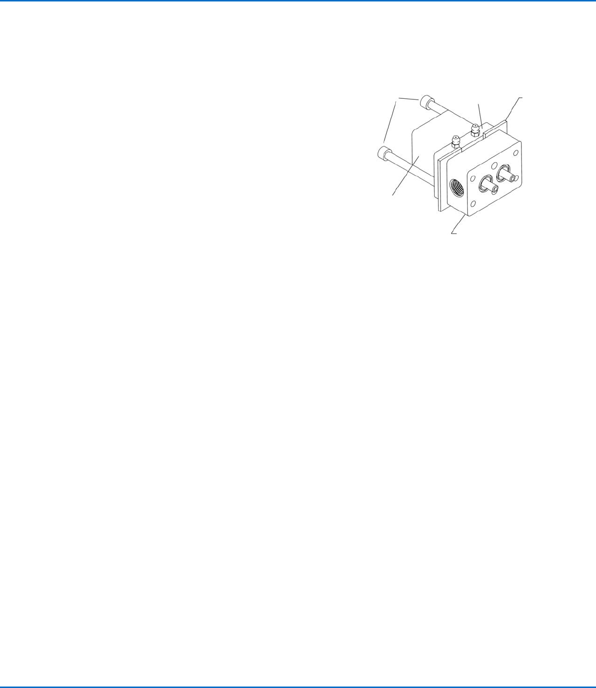
1. Remove the manifold and seat plate (8). Pry bar slots are provided.
2. Remove the air cylinder bolts (2) and wiggle the air cylinder apart.
If the assembly is frozen, use the pry bar slots on the valve body
(7) to separate the valve body (7) from the tie plate (5). Insert flat
pieces of metal between the valve body and the tie plate as per
Figure 1. Thread the manifold screws (36) into the back of the tie
plate and push the valve body apart. Apply uniform pressure to
prevent the body from cocking and bending the air cylinder shafts
(75).
3. Once apart, the parts should be cleaned. We recommend
overnight soaking in suitable solvent. All parts can be soaked
except the handle and air cylinder.
Manifold
screws
Tie plate
Metal
plate
Air cylinder
Valve body
Figure 1
Rebuilding the Autovalve
1. After cleaning, inspect the following components:
a. Seat plate (8) on sealing surface
b. Manually retract and extend the shafts (75) from air cylinder (1).
c. If the optional handle is used, connect air into the inlet and check 4-way action of cartridge valve (103).
2. Refer to page10 for a repair kit which contains lip seals, O-rings, and front seals.
3. Lubricate lip seals (3) and shafts (75) with auto grease (read SDS prior to use).
4. Insert four back lip seals (3): two into tie plate (5) and two into the valve body (7). The lip seals are two pieces: an O-ring
and a U-cup. They should always be installed with the O-ring facing the material inlets (body of the valve).
5. Push the air cylinder (1) thru the tie plate (5) and the valve body (7) and engage the screws (2).
6. Push front seal (13) and washer (12) onto adjustment screw (14). To prevent binding, apply auto grease to the threads on
the adjustment screws (14). Thread the seal and adjustment screw assembly into air cylinder shafts.
7. Assemble the seat plate (8) onto the valve body (7).
Final QC Check
Before the manifold is assembled, we recommend air be connected to the air cylinder (1) and the open / close function of the
front seals (13) be inspected for leakage.
The front seals cold flow into the proper shape as the valve is used. It may be necessary to pressurize the air cylinder, but not
the A & B fluids.
Series 400 Autovalve | Instructions / Parts Lists
5www.nordsonefd.com info@nordsonefd.com +1-401-431-7000 Sales and service of Nordson EFD dispensing systems are available worldwide.
P/N Ref. # Qty. Description
7702008 1A 1 Single Air Cylinder with Hardened SS Shafts
7702016 1B 1 Double Air Cylinder with Hardened SS Shafts (not shown)
7702295 2A 2 SHCS 10-24 x 2" long for Single Air Cylinder 450 Valve
7702325 2B 2 SHCS 10-24 x 3" long for Double Air Cylinder (not shown)
7702266 3A 4
Lip Seal: Viton
®
U-Cup and Viton O-ring
7702281 3B 4 Lip Seal: PU U-Cup and Viton O-ring
7702280 3C 4 Lip Seal: PTFE U-Cup and PTFE O-ring
7702277 3D 4 Lip Seal: UHMPE U-Cup and SS Spring
7702268 4 2 Grease Fitting, 10-32
7702270 5 1 Aluminum Tie Plate
7702813 6A 6 Viton O-ring
7702810 6B 6 EP O-ring
7702275 6C 6 PTFE Encapsulated O-ring
7702019 7A 1 Alum Body 9/16-18 Inlet Ports for 400 Valve
7702025 7B 1 SS Body 9/16-18 Inlet Ports for 400 Valve
7702026 8A 1 Stainless Steel Seat Plate for 400 Valve
7702028 9 2 Stainless Steel SHSS 1/4" Dia x 1" long for 400 Valve
7702297 10 2 Assembled Air Tube and Fitting 10-32 Thread
7702010 12A 2 Stainless Steel Washer for 400 Valve
7702011 13A 2 Front Seal for 400 Valve
7702012 14 2 Stainless Steel Adjustment Screw for 400 Valve
7702014 15 1 Adjustment Screw Driver for 400 Valve
7702364 16 1 Auto Grease Cartridge 3 oz (not shown)
7702373 17 1 Grease Gun
7702017 18 1 1/8" Short Arm Hex Key
Maintenance (continued)
NOTE: The O-rings in the lip seals face
the body (item 7). Consult factory for
additional seal combinations.