00194329-03.pdf - 第172页
Replacement instructions - Gantry c able and hose carrier SIPLACE HS / S / F 01/2007 Edition 172 2.2.9.1 Inst alling the new cable an d hose carrier If the gray T esa tape is still att ached to the guide pla te, replace …
Replacement instructions - Gantry cable and hose carrier SIPLACE HS / S / F
01/2007 Edition
171
All machine types: 2
: Dismantle the X cable clamp. If there is a short ribbon cable section in the clamp, keep this for
refitting later.
2
2
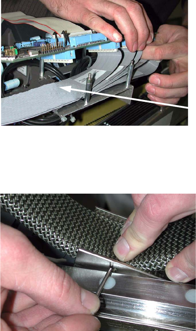
: Remove the entire cable and hose carrier from the machine.
: Relieve the strain on the pin by pressing the cable and hose carrier together.
Remove the pin from the diverter.It is not fixed in place.
No tools required.
2
Cable clamp
Replacement instructions - Gantry cable and hose carrier SIPLACE HS / S / F
01/2007 Edition
172
2.2.9.1 Installing the new cable and hose carrier
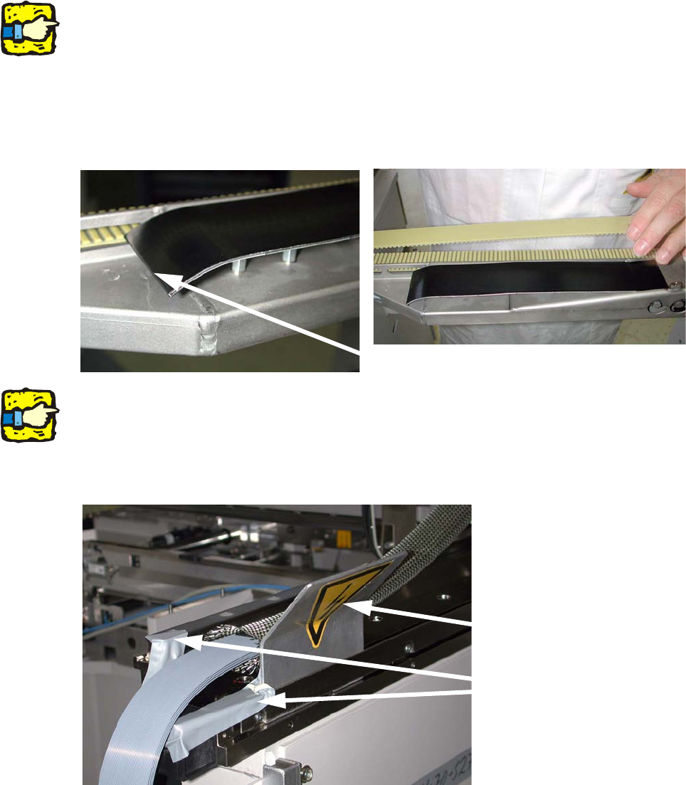
If the gray Tesa tape is still attached to the guide plate, replace it with the black protective film (item
no.: 03010326S01): 2
: Pull the existing adhesive tape off the gantry arm.
2
The guide plate can be bent very easily. 2
2
: Detach the protective film from the black adhesive tape and stick the tape to the cable plate on
the X axis gantry.
Make sure that the end of the protective film fully encloses the edge of the cable plate (approx.
2 cm).
2
2
Before you install the cable and hose carrier, cover all sharp edges on the machine frame, etc.
along the carrier with adhesive tape. The tape can be removed after installation. 2
A suitable piece of metal or plastic may be fitted in the gap beside the hood guide rail to prevent
the cable set slipping from the machine frame. 2
2
Stick nylon tape around the edge (approx. 2 cm)
Area covered with tape
Piece of metal or plastic
Replacement instructions - Gantry cable and hose carrier SIPLACE HS / S / F
01/2007 Edition
173
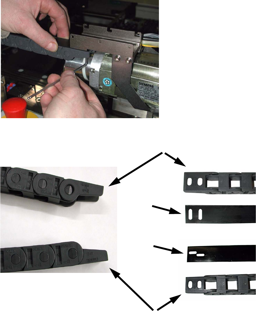
: Before fitting the power chain, round off the edges of the cover strip using a suitable grade of
emery paper.
: Fit the new chain with the cover strip at the top, starting at the cable and hose carrier mount
with one of the clamping plates provided.
Do not fully tighten the screws because you will later want to align the mount.
2
Top (cable and hose carrier mount)
Bottom (strain relief)
Correct installation position for the power chain
End of strip
on the bot-
tom
End of strip
on top
F4 / F4-6 / F5 / S-20 - S-27 HM / CS