Eaton 9155 8-15 kVA.pdf - 第43页
UPS 8 – 15 kV A, 230V 50/60 Hz output User ’ s Guide 1 022403 Revision D 43 Figure 44 Cable routing of T ie Cabinet Figure 45. T ie Cabinet’ s wiring diagram with three UPSs.
UPS 8 – 15 kVA, 230V 50/60 Hz output
User’s Guide
1022403
Revision D
42
Tie cabinets
The Tie Cabinets (TCs), provided by UPS manufacturer, has input connections up to three
parallel UPS modules. It is also possible to use two redundant UPS modules and one bypass
connection. This bypass option can be used for service or test purposes.
Note!
It is not allowed to feed the load simultaneously from mains (bypass) and
inverter(s) of the UPS unit(s). While turning the switch, where the bypass is
connected, ON/OFF, UPS should be on static bypass mode or shut down.
Note!
The maximum load supported by the system is limited to 15 kVA if there are two
UPSs and bypass connected to TC (See wiring diagrams below).
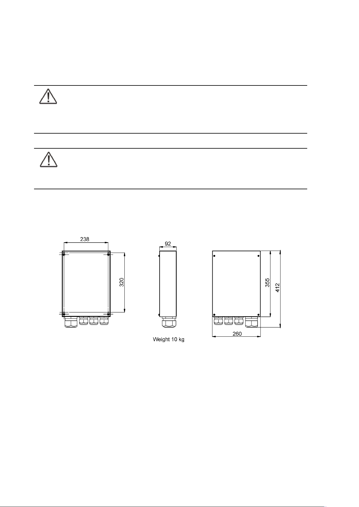
Terminals of the TC have two-wire connection (L1 and N) and ground terminals. The upper ground
terminal is for a load cable and the lower ground terminal is for UPSs. The wiring shall be done
according to the wiring diagrams. The terminals and cable routing is shown in Figure 44.
Figure 43. Dimensions of the Tie Cabinet
UPS 8 – 15 kVA, 230V 50/60 Hz output
User’s Guide
1022403
Revision D
43
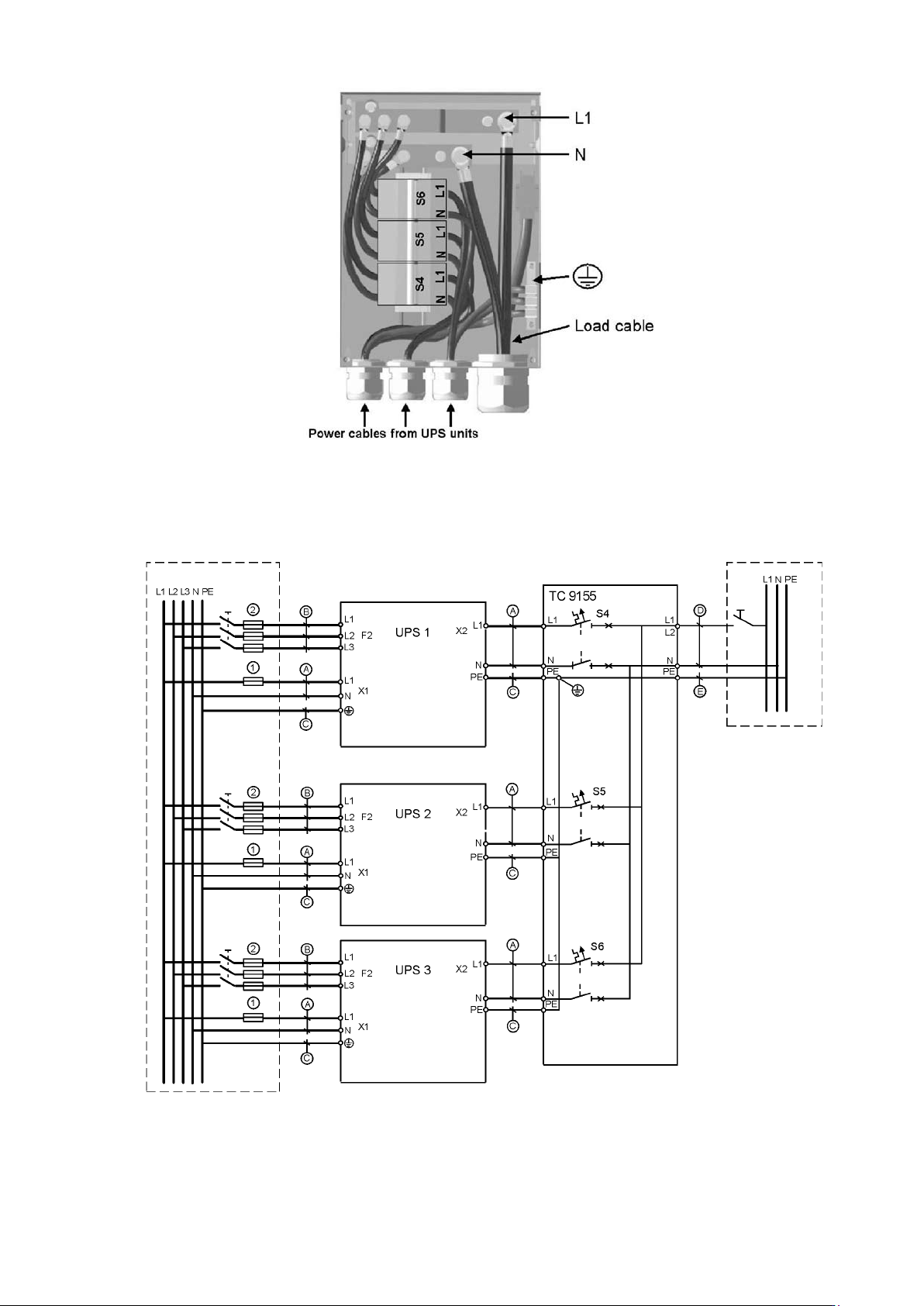
Figure 44 Cable routing of Tie Cabinet
Figure 45. Tie Cabinet’s wiring diagram with three UPSs.
UPS 8 – 15 kVA, 230V 50/60 Hz output
User’s Guide
1022403
Revision D
44
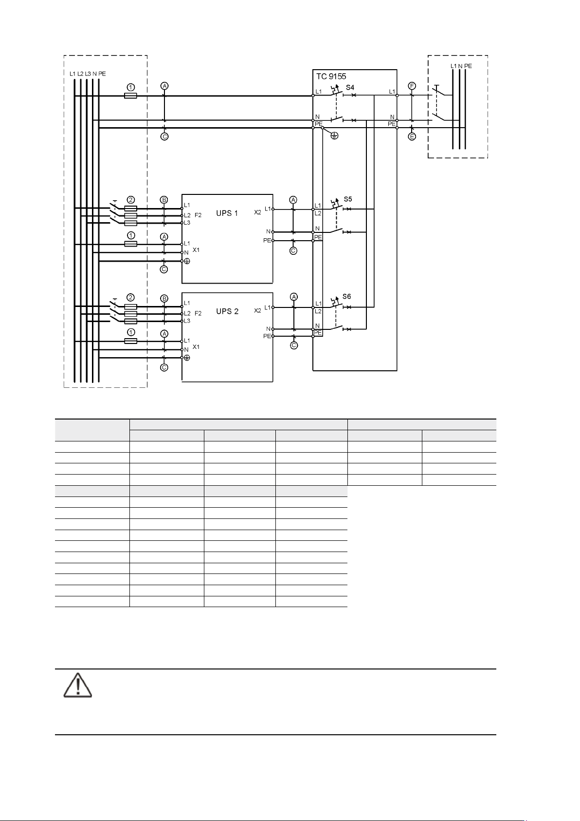
Figure 46. Tie Cabinet’s wiring diagram with two UPSs and bypass connected.
UPS Module
Bypass input X1 Rectifier input F2
Cable A Cable C Fuse 1 Cable B Fuse 2
8 kVA 10 mm
2
10 mm
2
50 A 2,5 mm
2
16 A
10 kVA 10 mm
2
10 mm
2
50 A 4 mm
2
20 A
12 kVA 16 mm
2
16 mm
2
63 A 6 mm
2
25 A
15 kVA 25 mm
2
16 mm
2
80 A 6 mm
2
32 A
TC Module Cable B Cable D Cable E
8 kVA 10 mm
2
10 mm
2
10 mm
2
10 kVA 10 mm
2
10 mm
2
10 mm
2
12 kVA 16 mm
2
16 mm
2
16 mm
2
15 kVA 25 mm
2
16 mm
2
25 mm
2
16 kVA 35 mm
2
16 mm
2
(35 mm
2
)*
20 kVA 35 mm
2
16 mm
2
(35 mm
2
)*
24 kVA 70 mm
2
35 mm
2
(70 mm
2
)*
30 kVA 70 mm
2
35 mm
2
(70 mm
2
)*
36 kVA 95 mm
2
50 mm
2
-
45 kVA 120 mm
2
70 mm
2
-
Table 47. Minimum cable and fuse rating for the different parallel system with installation procedure C
* (system bypass not allowed)
Note!
Protection fuses need to be used for load cabling if manufacturers Tie Cabinet (or
similar) not used.