00195398-0103-AI-01005Paket_DE_EN.pdf - 第43页
Asse mb ly In st ruct i on s 0100 5- Pac ket Edi t io n 12 /200 7 43 3.2 Require men t s Retrofitting m ay o nly b e pe rformed by S IPLACE s ervice technicia ns. 3 – SI P LA C E Pr o 5 .x – St ation comput er from SW 60…
Assembly Instructions 01005-Packet
Edition 12/2007
42
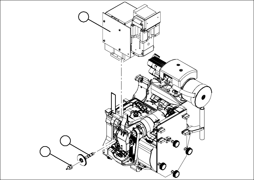
3.1 Function Description
In order to place 01005 components on a SIPLACE D1/D2/D4 machine, retrofitting as described
in the following section is required. In addition, certain prerequisites must be fulfilled. 3
The 12-Segment C&P head (DLM 3) must be equipped with the high-resolution camera (type 38).
The placement is executed with a specific sleeve and a 905 nozzle which must be attached to the
placement head. A special feeder is used to ensure optimal loading of the components. 3
Fig. 23 12-segment collect & place head with component camera, sleeve and nozzle
(4) Component Camera C&P, Type 38, 16x16 digital
(5) Sleeve 01005 (SP12 sleeve/270° degree partition)
(6) Nozzle, Type 905
1
3
2
Assembly Instructions 01005-Packet
Edition 12/2007
43
3.2 Requirements
Retrofitting may only be performed by SIPLACE service technicians. 3
– SIPLACE Pro 5.x
– Station computer from SW 604.01
– 12-segment C&P head (DLM 3)
– Retrofit kit [00119920-01-xx] consisting of:
– 03054857-01 1 x 01005 package for D4/D
2/D1
- 03057009-01 2 x adjustment sheet D4 / 1mm
- 03062029-01 2 x adjustment sheet D4 / 0.5mm
- 03063571-01 1 x locking plate D4 / 01005
- 00343075-01 2 x washers DIN 9021 - 3.2 - 140 HV - A2
- 03051870-01 1 x component camera C+P (type38) 16x16 digital
- 03054107-01 3 x sleeve SP12 comp. / 270 degree partition
- 03057320-01 12 x nozzle type 905 comp. ESD / 1x0.15
- 00195398-01 1 x assembly instructions 01005 package for D4/D2/D1, D+E
– Tape feeder 3x8mm S-Tape 01005 CO [00176100-xx]
3.2.1 Parts Required for SIPLACE D4 Machines
For optimization of the changeover table height for SIPLACE D4 machines, you require the follow-
ing parts: 3
– Adjustment sheets 1.0 mm and 0.5 mm for D4 machines (supplied with retrofitting kit)
– Locking plate with washers (supplied with retrofitting kit)
– Nozzle 901 or 925
– Changeover table measuring gauge
– CACCIA test program
For instructions about how to proceed, see from section 3.6.5 on page - 49 onwards. 3
3.2.2 Additional Documentation Required
– Operating manual for relevant machine
Assembly Instructions 01005-Packet
Edition 12/2007
44
3.2.3 Tools and Equipment
– Standard tool
3.3 Restrictions
– The 01005-package is only designed for use with D1/D2/D4-machines equipped with a C&P12
DLM3 head.
– The maximum length of the PCB is 230 mm.
– When using D4-machines, assembly must only take place in placement area 1 (PA1).
– Feeder with 01005-components may not be setup too far from the gantry suspension. De-
pending on the gantry suspension, the first six 3x8-feeder at maximum can be used for setup.
– If 01005-components are processed, the benchmark performance will drop approx. 22%.
3.4 Overview of Procedure
– Standard OnSite-MFU in order to document the original state of the machine before retrofitting.
– Replacement of existing component camera with new component camera.
– Replacement of existing sleeves with three new "SP12 sleeves comp." / 270 degree partition.
– Assignment of serial number for this sleeve to the segment.
– For SIPLACE D4 only: adjustment of changeover table height.
– Measurement of camera and placement head in SITEST - remeasure complete machine if
necessary.
– MFU with retrofitted machine using 01005 travel profile 33/34.
– Configuration of setup and component shape in SIPLACE Pro.
– Configuration at station computer.