00193360-02.pdf - 第22页
Retrofitting Instructions Splice Detection B asic Package S /F 11/2003 Edition 22 16 Inst alling the HUB 16 Fig. 16 - 1 Notes on installing the HUB : The h ub is fit ted beneath the side pane l of the in put conveyo r (F…
Retrofitting Instructions Splice Detection Basic Package S/F
11/2003 Edition
21
13 Tools
– Metric hex ball end wrench Set (also called “Allen” wrench)
– Diagonal cutters
– #1 Cross Point screwdriver (also called a “Phillips Head” screwdriver)
– A small flat bladed screwdriver
14 Parts
Contents Splice Detection Basic Package S / F
(item no.: 00116935-xx) 14
Pieces Description Item no.:
- 1 Retrofitting Instructions Basic Package 00193360-01
- 1 Retrofitting Instructions Table Controller 00193361-01
- 1 Retrofitting Instructions Splice Sensor 2x8 mm 00193365-01
- 1 Hub Unit 00366091-02
- Various installation material
- 1 Cable Hub - TC long 00368249-01
- 1 Cable Hub - TC short 00368250-01
- Cable Power Supply HUB 00368322-01
- 1 Serial Cable to station computer 00368431-01
- Machine Cover 1 modified 00368324-01
- 1 Machine Cover 2 modified 00368553-01
15 Preparation
: Pull out all feeder tables
: Switch the machine off at the main switch.
: Interrupt the power supply to the machine to prevent the risk of electric shock.
: Read the installation instructions carefully.
Retrofitting Instructions Splice Detection Basic Package S/F
11/2003 Edition
22
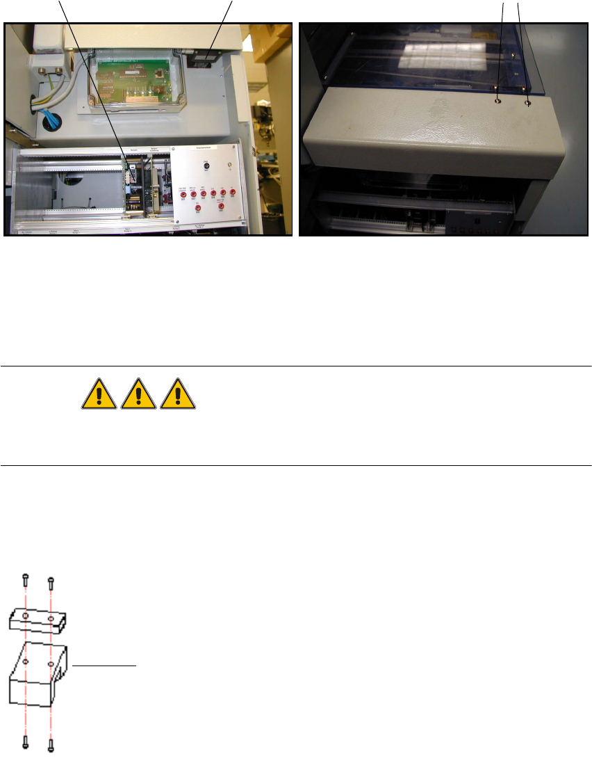
16 Installing the HUB
16
Fig. 16 - 1 Notes on installing the HUB
: The hub is fitted beneath the side panel of the input conveyor (Fig. 6 - 1 left).
: Loosen the screws for fixing the contact plug of the input conveyor (Fig. 6 - 1 right).
DANGER
Before starting the placement machine connect and bolt the HUB electrical conducting with the
machine frame! 16
: Replace the spacer with the mount for the hub, then reinstall the hub and contact plug (Fig. 6
- 2). Don't forget to adjust the contact plug afterwards.
16
Fig. 16 - 2 Contact plug and spacer
Servo unit
5x10 screws
Contact plug
Spacer
Retrofitting Instructions Splice Detection Basic Package S/F
11/2003 Edition
23
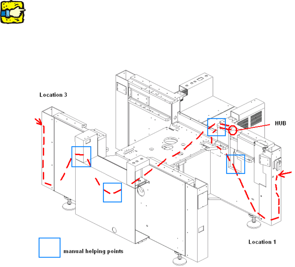
17 Cable route
The following diagram (Fig. 7 - 1) shows the route that the cables should follow from the table con-
trollers to the hub. 17
17
Please use the pilot wire to help you through difficult sections. 17
17
17
The figure shows a number of manual helping points, i.e. points at which you can reach the cable
with your hand. 17
17
Fig. 17 - 1 Cable route through the machine
17
17
17