00193360-02.pdf - 第30页
Retrofitting Instructions Splice Detection B asic Package S /F 11/2003 Edition 30 19 Connecting to the st ation computer : Plug t he seri al cable into the HUB . : Use the pilot wi re to pull the se rial cable to the sta…
Retrofitting Instructions Splice Detection Basic Package S/F
11/2003 Edition
29
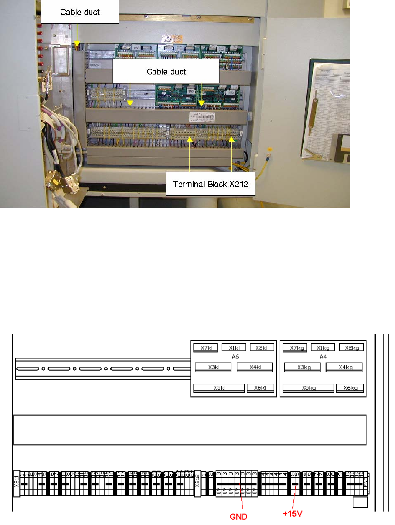
18 Power Supply for the HUB Unit
18
Fig. 18 - 1 Connecting the power supply for the hub
: Start at terminal block X212 (Fig. 8 - 1)
: Connect the voltage terminals as shown in Fig. 8 - 2.
: Connect the first wire (white or blue) of power supply cable to a GND terminal.
: Connect the brown wire to a +15 V terminal.
. 18
Fig. 18 - 2 Terminals for power supply
: Run the cable through the existing cable ducts to the hub.
Retrofitting Instructions Splice Detection Basic Package S/F
11/2003 Edition
30
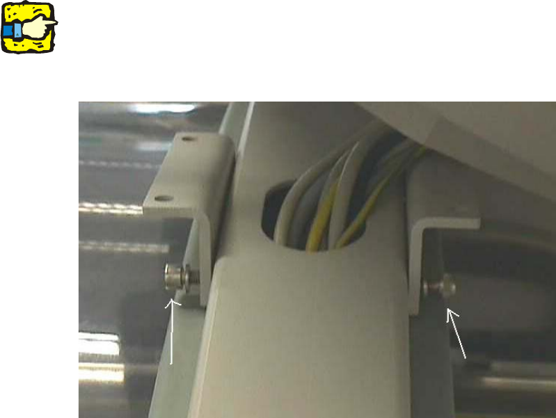
19 Connecting to the station computer
: Plug the serial cable into the HUB.
: Use the pilot wire to pull the serial cable to the station computer. Loosen the two screws at the
side to make more room for the plug (Fig. 9 - 1).
: Plug the serial cable supplied into the free COM port on the station computer
19
It is better to do this work with 2 persons. 19
19
19
19
Fig. 19 - 1 Screws for detaching the station computer mount
19
19
19
19
19
19
Retrofitting Instructions Splice Detection Basic Package S/F
11/2003 Edition
31
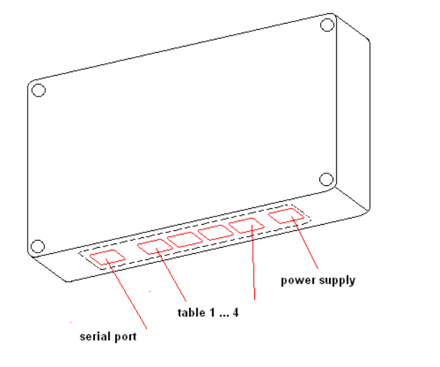
20 Connector pin assignment on the hub
: Plug the existing cables at the hub into the associated sockets (Fig. 10 - 1).
20
Fig. 20 - 1 Connector pin assignment on the hub
20
20
20