ax501-A08.pdf - 第4页
Chapter A8 Service Manual 4022 593 51915 A.152 AX-301/501, AX-3/5 08.05 SYSTEM A08.fm A8.2 Decommissoning polic y The f ollowin g items can become solid w aste after use: • Printed cir cuit boards • Trans for mers • Aut …
4022 593 51915 Service Manual
08.05 AX-301/501, AX-3/5 A.151
A08.fm
Chapter A8
SYSTEM
When repairable modules or parts require special tools or knowledge to perform the
repair, a repair channel is defined by Assembléon. Depending on the type of repair
that is provided, the module or part can be exchanged for a refurbished one (repair
option RO) or is returned after being repaired (repair option RC).
A8.1.2 Repair strategy per module
The repair strategy is different per module, depending on it's properties like
modularity, necessary tools, necessary knowledge, costs, etc.
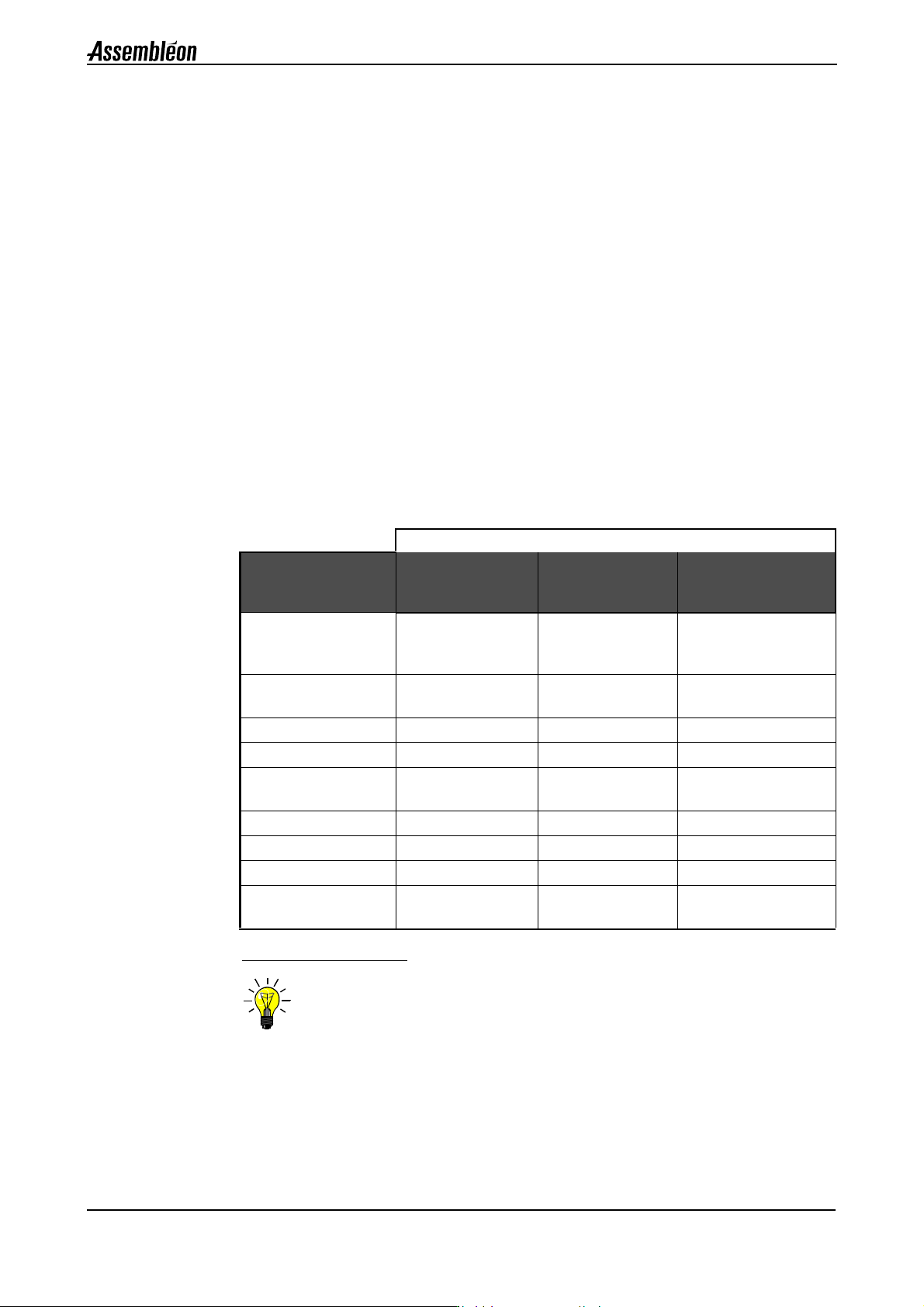
The table below gives an overview of the available repair strategies per module.
Example:
1. The table shows that for the placement head, on-line repair of the machine
involves an exchange of the complete module. This module cannot be repaired
off-line by the customer but only by returning it to Assembléon.
2. The table shows that for the transport controller, on-line repair of the machine
involves an exchange of the complete module. This module can be repaired off-
line by the customer by exchanging spare parts. One of these parts, the
embedded process controller, can be returned to Assembléon for repair.
Figure 108 Available repair strategy
NOTE: The repair strategy is explained in more detail in chapter 8 of each part: base,
transport and pick & place.
Available repair strategy
Module
On-line repair at
customer site by
exchange of:
Off-line repair at
customer site by
exchange of:
Return to Assembléon
as repairable part
Placement robot Complete module
Pneumatic controller
Spare parts Complete module in case
of failure of none spare
parts.
Placement controller Complete module Spare parts Embedded process
controller
Placement head Complete module N.A. Complete module
Toolbit exchange unit Complete module N.A. N.A.
Transport controller Complete module Spare parts Embedded process
controller
System controller Complete module N.A. Complete module
Mains supply unit Complete module Spare parts N.A.
Feeder Trolley Complete module Spare parts N.A.
Other machine parts
(base and transport)
N.A. Spare parts N.A.

Chapter A8
Service Manual 4022 593 51915
A.152 AX-301/501, AX-3/5 08.05
SYSTEM
A08.fm
A8.2 Decommissoning policy
The following items can become solid waste after use:
• Printed circuit boards
• Transformers
• Automatic fuses / motor switches
• Batteries
• Lamps
• Relays /contact elements.
After Decommissoning, more than 80% of the machine can be recycled.
Some parts become solid waste.
Disposal of solid waste should be done in accordance to local legislation.
This differs per country.
A8.3 Spare parts
A8.3.1 Glossary of terms
• Item number. . . Four digit number to identify the spare part in this manual,
consisting of a two digit module number and a two-digit
sequential number for each spare part.
• Part of item . . . If a spare part is a part of a higher assembly, part of item
shows which assembly.
• Ordering code . . The code number with which the spare part can be ordered
at your regional service center;
• Description . . . . Name of the spare part.
• Qty/ mod . . . . . The number of times the part is used within the module.
When two numbers are listed the first number is applicable
to the 3 base, the second to 5 base.
When this field is left empty the item either equals the
module or the item is not directly related to the machine
configuration.
• Priority Indictor A part can be a priority spare part, meaning it is of vital
importance for running the machine. If a spare part is a
priority spare part, it will be declared as “Y”, otherwise a “-
” is shown. A priority spare part is assumed to be stocked
regionally.
• Repair options. . ‘RO’: The defective item is replaced (swapped), after
sending it back, by a part with equal form, fit and
function.
‘RC’: Customized repair, after repair the same item is
sent back.
‘-’ :No repair, discard item,
see A8.2 Decommissoning policy
• Replacement instruction
For this spare part a replacement instruction is available.
• Remarks . . . . . . Provide extra information.

4022 593 51915 Service Manual
08.05 AX-301/501, AX-3/5 A.153
A08.fm
Chapter A8
SYSTEM
A8.3.2 Parts overview
A8.3.3 Base . . . . . . . . . . . . . . . . . . . . . . . . . . . . . . . . . . . . . . . . A.154
A8.3.4 Mains supply unit and transformer . . . . . . . . . . . . . . . . . . . . A.156
A8.3.4.1 Mains supply unit, PA 1120/04 and newer,
PA 1121/04 and newer. . . . . . . . . . . . . . . . . . . . . . . . . A.156
A8.3.4.2 Mains supply unit, PA 1120/03 and older,
PA 1121/03 and older . . . . . . . . . . . . . . . . . . . . . . . . . A.158
A8.3.4.3 Transformer . . . . . . . . . . . . . . . . . . . . . . . . . . . . . . . . A.160
A8.3.5 Air supply unit . . . . . . . . . . . . . . . . . . . . . . . . . . . . . . . . . A.162
A8.3.6 Electrical distribution rail . . . . . . . . . . . . . . . . . . . . . . . . . . A.164
A8.3.7 System controller . . . . . . . . . . . . . . . . . . . . . . . . . . . . . . . A.166
A8.3.8 Base CAN module . . . . . . . . . . . . . . . . . . . . . . . . . . . . . . . A.168
A8.3.9 Trolley lift . . . . . . . . . . . . . . . . . . . . . . . . . . . . . . . . . . . . A.170
A8.3.9.1 Trolley lift 4022-510-8300x. . . . . . . . . . . . . . . . . . . . . . A.170
A8.3.9.2 Trolley lift 4022-510-7995x. . . . . . . . . . . . . . . . . . . . . . A.172
A8.3.10 Transport controller . . . . . . . . . . . . . . . . . . . . . . . . . . . . . . A.174
A8.3.10.1 Transport controller 4022-594-1570X . . . . . . . . . . . . . . . A.174
A8.3.10.2 Transport controller 4022-592-4225X . . . . . . . . . . . . . . . A.176
A8.3.10.3 Transport controller 4022-594-4200x . . . . . . . . . . . . . . . A.178
A8.3.11 Transport CAN module . . . . . . . . . . . . . . . . . . . . . . . . . . . . A.180
A8.3.12 Transport beam . . . . . . . . . . . . . . . . . . . . . . . . . . . . . . . . . A.182
A8.3.13 Front and rear transport rails. . . . . . . . . . . . . . . . . . . . . . . . A.184
A8.3.14 Board support. . . . . . . . . . . . . . . . . . . . . . . . . . . . . . . . . . A.186
A8.3.15 Placement controllers . . . . . . . . . . . . . . . . . . . . . . . . . . . . A.188
A8.3.15.1 Placement controller PA 1800/01 . . . . . . . . . . . . . . . . . . A.188
A8.3.15.2 Placement controller PA 1800/00 . . . . . . . . . . . . . . . . . . A.190
A8.3.16 Robots. . . . . . . . . . . . . . . . . . . . . . . . . . . . . . . . . . . . . . . A.192
A8.3.17 Placement head, toolbits and toolbit exchange unit . . . . . . . . A.194
A8.3.18 CV camera . . . . . . . . . . . . . . . . . . . . . . . . . . . . . . . . . . . . A.196
A8.3.19 Cooling rack . . . . . . . . . . . . . . . . . . . . . . . . . . . . . . . . . . . A.197
NOTE: For spare parts information concerning Tape Loading Unit, Feeder Storage
Cart, Twin Bulk Feeder and Intelligent Tape Feeder see separate “Intelligent
Feeder Manual”.