YSM10安装调整(eng).pdf - 第3页
For Ser v ice E n gineer Service Information SI1610004E -000= YSM10_Proced ures for the adjustmen ts required after installing a machine 3/107 5.7.3 How to analyze the “VgChart” . ........................................…

For Service Engineer
Service Information
SI1610004E-000= YSM10_Procedures for the adjustments required after installing a machine
2/107
Table of contents
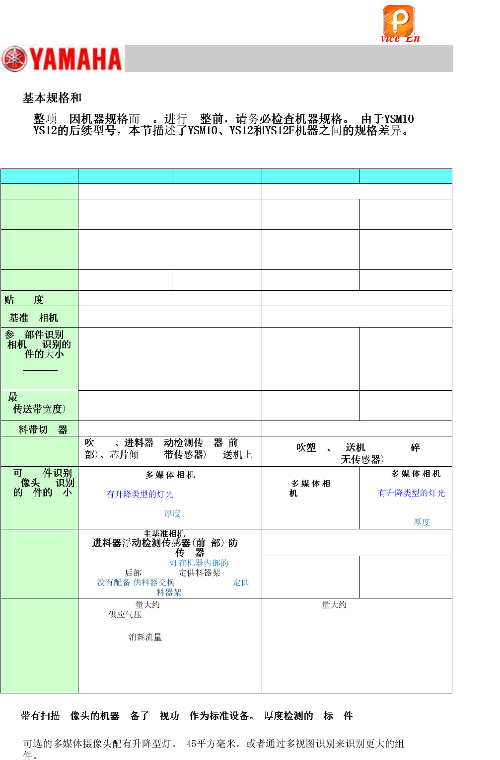
1. Basic specifications and options . .................................................................................................. 4
2. Jigs and tools required for the adjustment . .................................................................................. 5
2.1 Jigs for the “Lightness” adjustment of the cameras . .................................................................. 5
2.2 board and components required for the ACP-Chip adjustment . ...................................... 5
2.3 Station and components required for the “ACP-Station” adjustment . ....................................... 6
2.4 Jigs and tools required for installing a machine . ....................................................................... 6
2.5 Other jigs required for the adjustment . ...................................................................................... 7
3. Installation of the machine. ............................................................................................................. 8
3.1 Remove the shipping brackets . ................................................................................................. 8
3.2 Positions to set the levels and production line alignment . ......................................................... 9
3.3 When the monitor interferes with the adjoining machine . ........................................................ 10
3.4 Connect to the power source and air supply . .......................................................................... 12
3.5 Connect the signal cable . ........................................................................................................ 13
3.6 Safety check before the adjustment . ....................................................................................... 13
4. Workflow before the mounting adjustment . ................................................................................ 14
4.1 Basic workflow before the mounting adjustment . .................................................................... 14
4.2 System data backup . ............................................................................................................... 15
4.3 Read the board data “MCH_SETUP” . ..................................................................................... 15
4.4 Start up the CalibSm adjustment utility . ................................................................................... 16
4.5 Axis . ......................................................................................................................................... 17
4.5.1 Check the “Motor Reference” . ............................................................................................................ 17
4.5.2 “Dual Drive Offset” adjustment for the Y-axis . .................................................................................... 18
4.6 “Orthogonalization Level” adjustment . ..................................................................................... 19
4.7 “BaseMACS” adjustment . ........................................................................................................ 22
4.8 “Vacuum Level” adjustment . .................................................................................................... 23
4.8.1 Automatic adjustment (“All Exec”) .............................................................................................. 23
4.8.2 Manual adjustment (“Manual”) . .......................................................................................................... 27
4.9 “Fiducial camera relative pos.” adjustment (Option) . ............................................................... 28
4.10 “MultiMACS Light” adjustment (Option) . .................................................................................. 30
4.11 Scan camera - “Camera Position” adjustment. ........................................................................ 31
4.12 Multi camera – “Camera Pos.” adjustment (Option) . ............................................................... 32
4.13 “Head Offset XY” adjustment . .................................................................................................. 34
4.14 Check the operation of the blow station (Option) . ................................................................... 38
4.15 “Measure s” for the side view camera . ............................................................................. 38
5. “ACP-Chip” adjustment . ............................................................................................................... 39
5.1 Requirements for the adjustment . ........................................................................................... 39
5.2 Check the option setting . ......................................................................................................... 40
5.3 Basic flow of the ACP adjustment . .......................................................................................... 42
5.4 Preparation for the ACP-Chip adjustment . .............................................................................. 43
5.5 ACP-Chip accuracy adjustment . .............................................................................................. 45
5.5.1 Start up the ACP-Chip utility and perform setting for the adjustment ................................................. 45
5.5.2 Mounting, measurement and correction by the ACP-Chip . ................................................................ 46
5.5.3 Feed back the correction values when the “AMF Index 1“ falls below 1.0 ......................................... 48
5.6 ACP-Chip adjustment for the Multi camera (Option) . .............................................................. 49
5.6.1 Camera Acc. Copy . ............................................................................................................................ 49
5.6.2 “ACP-Chip” adjustment for the multi camera . .................................................................................... 50
5.7 “AMF Index” and “VgChart” . .................................................................................................... 51
5.7.1 About “AMF Index” . ............................................................................................................................ 51
5.7.2 Check the “VgChart” window . ............................................................................................................ 52
该文档是极速PDF编辑器生成,
如果想去掉该提示,请访问并下载:
http://www.jisupdfeditor.com/

For Service Engineer
Service Information
SI1610004E-000= YSM10_Procedures for the adjustments required after installing a machine
3/107
5.7.3 How to analyze the “VgChart” . ........................................................................................................... 53
6. “ACP-Station” adjustment (with a QFP and the Multi camera) . ........................................ 55
6.1 General description of the “ACP-Station” adjustment . ............................................................ 55
6.2 Required jigs . ........................................................................................................................... 56
6.3 Flow of the adjustment . ............................................................................................................ 57
6.4 Read the board data “MCH_SETUP” . ..................................................................................... 58
6.5 Initial setup for the FAMF station . ............................................................................................ 59
6.5.1 When using a standard FAMF station . ............................................................................................... 59
6.5.2 When using a small FAMF station . .................................................................................................... 60
6.6 Check the board data . ............................................................................................................. 61
6.6.1 Information required for the adjustment . ............................................................................................ 61
6.6.2 Change the “Board Size Height” to 10.0mm . ..................................................................................... 63
6.7 Before starting the “ACP-Station” adjustment . ........................................................................ 64
6.7.1 Setting for the items on the left side of the window . ........................................................................... 64
6.7.2 Setting for the items on the right side of the “AutoRun/Measure” window ......................................... 65
6.8 Run the program . ..................................................................................................................... 69
6.9 Check the Total Index . ............................................................................................................. 71
6.9.1 “FinishLog” confirmation window . ...................................................................................................... 71
6.9.2 Export the “Result.dat” accuracy data after the adjustment . .............................................................. 73
6.9.3 Other tabs ........................................................................................................................................... 73
6.9.4 “Feedback log” confirmation window. ................................................................................................. 75
6.9.5 Export the accuracy data “Result.dat” before the adjustment . ........................................................... 75
6.9.6 “Error Log” confirmation window . ....................................................................................................... 75
7. Items to be checked after performing the accuracy adjustment . ............................................. 76
7.1 Check the Edge clamp position . .............................................................................................. 76
7.2 “FeederPos” . ............................................................................................................................ 76
7.2.1 Feeder pickup position XY adjustment . ............................................................................................. 76
7.2.2 Feeder Pickup position Z adjustment . ................................................................................................ 78
7.2.3 Plate check ......................................................................................................................................... 79
7.3 Check the operation of the “ Change” function (Option). .................................................. 81
7.4 Check the operation of the tray changer (Option) . .................................................................. 82
8. Check the machine setting . .......................................................................................................... 83
9. Move the board data for the adjustment . .................................................................................... 83
10. Back up the system data and bring back the data . .................................................................... 83
10.1 System data backup . ............................................................................................................... 83
10.2 System full backup . .................................................................................................................. 83
10.3 How to bring back the adjusted data . ...................................................................................... 84
11. Basic adjustments required when “AMF index 1” falls below 1.000 . ....................................... 86
11.1 Flow of the basic adjustment . .................................................................................................. 86
11.2 Workflow for when “AMF Index 1“ falls below 1.000 . .............................................................. 87
11.3 Adjustments related to the mounting accuracy. ....................................................................... 88
11.3.1 Fiducial camera - “” adjustment. .................................................................................................. 88
11.3.2 Fiducial camera – “Lightness” adjustment . ........................................................................................ 89
11.3.3 Scan camera – “Lightness” adjustment. ............................................................................................. 92
11.3.4 Scan camera -“” adjustment . ....................................................................................................... 96
11.3.5 “Head Offset Z” adjustment . ............................................................................................................... 98
11.3.6 “PCB Height” adjustment . .................................................................................................................. 99
11.3.7 Multi camera – “Lightness” adjustment (Option) . ............................................................................. 102
11.3.8 Multi camera – “” adjustment (Option) . ...................................................................................... 106
该文档是极速PDF编辑器生成,
如果想去掉该提示,请访问并下载:
http://www.jisupdfeditor.com/
For Service Engineer
Service Information
SI1610004E-000= YSM10_Procedures for the adjustments required after installing a machine
4/107
1.
@@
YSM10 (10 Heads)
YSM10 (5 Heads)
YS12
YS12F
System
VGOS V40 (Windows 7)
VGOS V30 (Windows XP)
Feeder
(SS, ZS)
(ZS: Non-stop feeder replacement function is
NOT available.)
Electric feeder
Electric feeder
Front side
24-reel fixed feeder bank × 2 (No machines with
the Feeder Exchange Carriage or 60-reel fixed
feeder bank.)
Front side 24/60-reel
fixed feeder bank) &
Feeder exchange
carriage
Front side 24-reel fixed
feeder bank × 2 &
Feeder exchange
carriage
Number of heads
10
(12mm pitch)
5
(24mm pitch)
10
(12mm pitch)
5
(24mm pitch)
35μm (μ+3σ, chip)
50μm (μ+3σ, chip)
Right side (Standard)
Field of view : 8mm sq.
Right side (Standard)
Field of view : 5mm sq.
@ @ @
@@@@@
(XY * Z)
(*1)
[Digital 3]
12mm sq.
6.5mm thick
(*1)
[Digital 3]
8mm sq.
6.5mm thick
[Digital 5]
*( )
32mm sq.
15.0mm thick
@ @ @ @ @ @
HHH II
460mm
360mm (With sATS)
460mm
460mm
360mm (With ATS15)
Standard
Option
Standard
specification
H H H
II HHH II@@@
@ @ @
HHH II
@ @ @
(XY * Z)
[Digital 5, 6]
* (Standard) 45mm
sq. (55mm sq.)
15mm
(*2)
[Digital
5, 6]
20mm sq.
6.5mm thick
[Digital 6]
*
(Option)
32mm sq.
15.0mm
ANC,
HH @@ II
sATS15, LED ,
24-reel ,
( or 60-reel
.)
Rear side 24/60-reel fixed
feeder bank & 24-reel
feeder exchange carriage
ATS15, Rear side 24
/60-reel fixed feeder
bank
. 1,270kg
: 0.45MPa or higher Set
pressure: 0.40 - 0.41MPa
. 1,250kg
Supplied air pressure: 0.45MPa or higher
Set pressure: 0.40 - 0.41MPa
: 290L/min [ANR]
(Instantaneous maximum flow when the tape
cutter is installed.)
Air consumption flow rate: 310 ℓ /min [ANR]
(Instantaneous maximum flow when the tape
cutter is installed.)
Power capacity : 7.0 kVA
(Conductor cross-section area of the supply
cable : 4.0mm
2
or more)
Power capacity : 4.9 kVA
(Conductor cross-section area of the supply
cable : 2.5mm
2
or more)
Table 1
*1: H H H : [Size]: 0402
to 3216 [Thickness]: 1.2mm or less)
*2:
该文档是极速PDF编辑器生成,
如果想去掉该提示,请访问并下载:
http://www.jisupdfeditor.com/