YSM10安装调整(eng).pdf - 第4页
For Ser v ice E n gineer Service Information SI1610004E -000= YSM10_Proced ures for the adjustmen ts required after installing a machine 4/107 1. �…

For Service Engineer
Service Information
SI1610004E-000= YSM10_Procedures for the adjustments required after installing a machine
3/107
5.7.3 How to analyze the “VgChart” . ........................................................................................................... 53
6. “ACP-Station” adjustment (with a QFP and the Multi camera) . ........................................ 55
6.1 General description of the “ACP-Station” adjustment . ............................................................ 55
6.2 Required jigs . ........................................................................................................................... 56
6.3 Flow of the adjustment . ............................................................................................................ 57
6.4 Read the board data “MCH_SETUP” . ..................................................................................... 58
6.5 Initial setup for the FAMF station . ............................................................................................ 59
6.5.1 When using a standard FAMF station . ............................................................................................... 59
6.5.2 When using a small FAMF station . .................................................................................................... 60
6.6 Check the board data . ............................................................................................................. 61
6.6.1 Information required for the adjustment . ............................................................................................ 61
6.6.2 Change the “Board Size Height” to 10.0mm . ..................................................................................... 63
6.7 Before starting the “ACP-Station” adjustment . ........................................................................ 64
6.7.1 Setting for the items on the left side of the window . ........................................................................... 64
6.7.2 Setting for the items on the right side of the “AutoRun/Measure” window ......................................... 65
6.8 Run the program . ..................................................................................................................... 69
6.9 Check the Total Index . ............................................................................................................. 71
6.9.1 “FinishLog” confirmation window . ...................................................................................................... 71
6.9.2 Export the “Result.dat” accuracy data after the adjustment . .............................................................. 73
6.9.3 Other tabs ........................................................................................................................................... 73
6.9.4 “Feedback log” confirmation window. ................................................................................................. 75
6.9.5 Export the accuracy data “Result.dat” before the adjustment . ........................................................... 75
6.9.6 “Error Log” confirmation window . ....................................................................................................... 75
7. Items to be checked after performing the accuracy adjustment . ............................................. 76
7.1 Check the Edge clamp position . .............................................................................................. 76
7.2 “FeederPos” . ............................................................................................................................ 76
7.2.1 Feeder pickup position XY adjustment . ............................................................................................. 76
7.2.2 Feeder Pickup position Z adjustment . ................................................................................................ 78
7.2.3 Plate check ......................................................................................................................................... 79
7.3 Check the operation of the “ Change” function (Option). .................................................. 81
7.4 Check the operation of the tray changer (Option) . .................................................................. 82
8. Check the machine setting . .......................................................................................................... 83
9. Move the board data for the adjustment . .................................................................................... 83
10. Back up the system data and bring back the data . .................................................................... 83
10.1 System data backup . ............................................................................................................... 83
10.2 System full backup . .................................................................................................................. 83
10.3 How to bring back the adjusted data . ...................................................................................... 84
11. Basic adjustments required when “AMF index 1” falls below 1.000 . ....................................... 86
11.1 Flow of the basic adjustment . .................................................................................................. 86
11.2 Workflow for when “AMF Index 1“ falls below 1.000 . .............................................................. 87
11.3 Adjustments related to the mounting accuracy. ....................................................................... 88
11.3.1 Fiducial camera - “” adjustment. .................................................................................................. 88
11.3.2 Fiducial camera – “Lightness” adjustment . ........................................................................................ 89
11.3.3 Scan camera – “Lightness” adjustment. ............................................................................................. 92
11.3.4 Scan camera -“” adjustment . ....................................................................................................... 96
11.3.5 “Head Offset Z” adjustment . ............................................................................................................... 98
11.3.6 “PCB Height” adjustment . .................................................................................................................. 99
11.3.7 Multi camera – “Lightness” adjustment (Option) . ............................................................................. 102
11.3.8 Multi camera – “” adjustment (Option) . ...................................................................................... 106
该文档是极速PDF编辑器生成,
如果想去掉该提示,请访问并下载:
http://www.jisupdfeditor.com/
For Service Engineer
Service Information
SI1610004E-000= YSM10_Procedures for the adjustments required after installing a machine
4/107
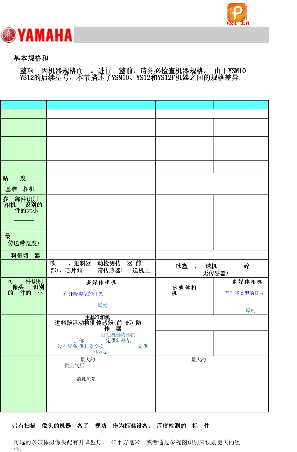
1.
@@
YSM10 (10 Heads)
YSM10 (5 Heads)
YS12
YS12F
System
VGOS V40 (Windows 7)
VGOS V30 (Windows XP)
Feeder
(SS, ZS)
(ZS: Non-stop feeder replacement function is
NOT available.)
Electric feeder
Electric feeder
Front side
24-reel fixed feeder bank × 2 (No machines with
the Feeder Exchange Carriage or 60-reel fixed
feeder bank.)
Front side 24/60-reel
fixed feeder bank) &
Feeder exchange
carriage
Front side 24-reel fixed
feeder bank × 2 &
Feeder exchange
carriage
Number of heads
10
(12mm pitch)
5
(24mm pitch)
10
(12mm pitch)
5
(24mm pitch)
35μm (μ+3σ, chip)
50μm (μ+3σ, chip)
Right side (Standard)
Field of view : 8mm sq.
Right side (Standard)
Field of view : 5mm sq.
@ @ @
@@@@@
(XY * Z)
(*1)
[Digital 3]
12mm sq.
6.5mm thick
(*1)
[Digital 3]
8mm sq.
6.5mm thick
[Digital 5]
*( )
32mm sq.
15.0mm thick
@ @ @ @ @ @
HHH II
460mm
360mm (With sATS)
460mm
460mm
360mm (With ATS15)
Standard
Option
Standard
specification
H H H
II HHH II@@@
@ @ @
HHH II
@ @ @
(XY * Z)
[Digital 5, 6]
* (Standard) 45mm
sq. (55mm sq.)
15mm
(*2)
[Digital
5, 6]
20mm sq.
6.5mm thick
[Digital 6]
*
(Option)
32mm sq.
15.0mm
ANC,
HH @@ II
sATS15, LED ,
24-reel ,
( or 60-reel
.)
Rear side 24/60-reel fixed
feeder bank & 24-reel
feeder exchange carriage
ATS15, Rear side 24
/60-reel fixed feeder
bank
. 1,270kg
: 0.45MPa or higher Set
pressure: 0.40 - 0.41MPa
. 1,250kg
Supplied air pressure: 0.45MPa or higher
Set pressure: 0.40 - 0.41MPa
: 290L/min [ANR]
(Instantaneous maximum flow when the tape
cutter is installed.)
Air consumption flow rate: 310 ℓ /min [ANR]
(Instantaneous maximum flow when the tape
cutter is installed.)
Power capacity : 7.0 kVA
(Conductor cross-section area of the supply
cable : 4.0mm
2
or more)
Power capacity : 4.9 kVA
(Conductor cross-section area of the supply
cable : 2.5mm
2
or more)
Table 1
*1: H H H : [Size]: 0402
to 3216 [Thickness]: 1.2mm or less)
*2:
该文档是极速PDF编辑器生成,
如果想去掉该提示,请访问并下载:
http://www.jisupdfeditor.com/
For Service Engineer
Service Information
SI1610004E-000= YSM10_Procedures for the adjustments required after installing a machine
5/107
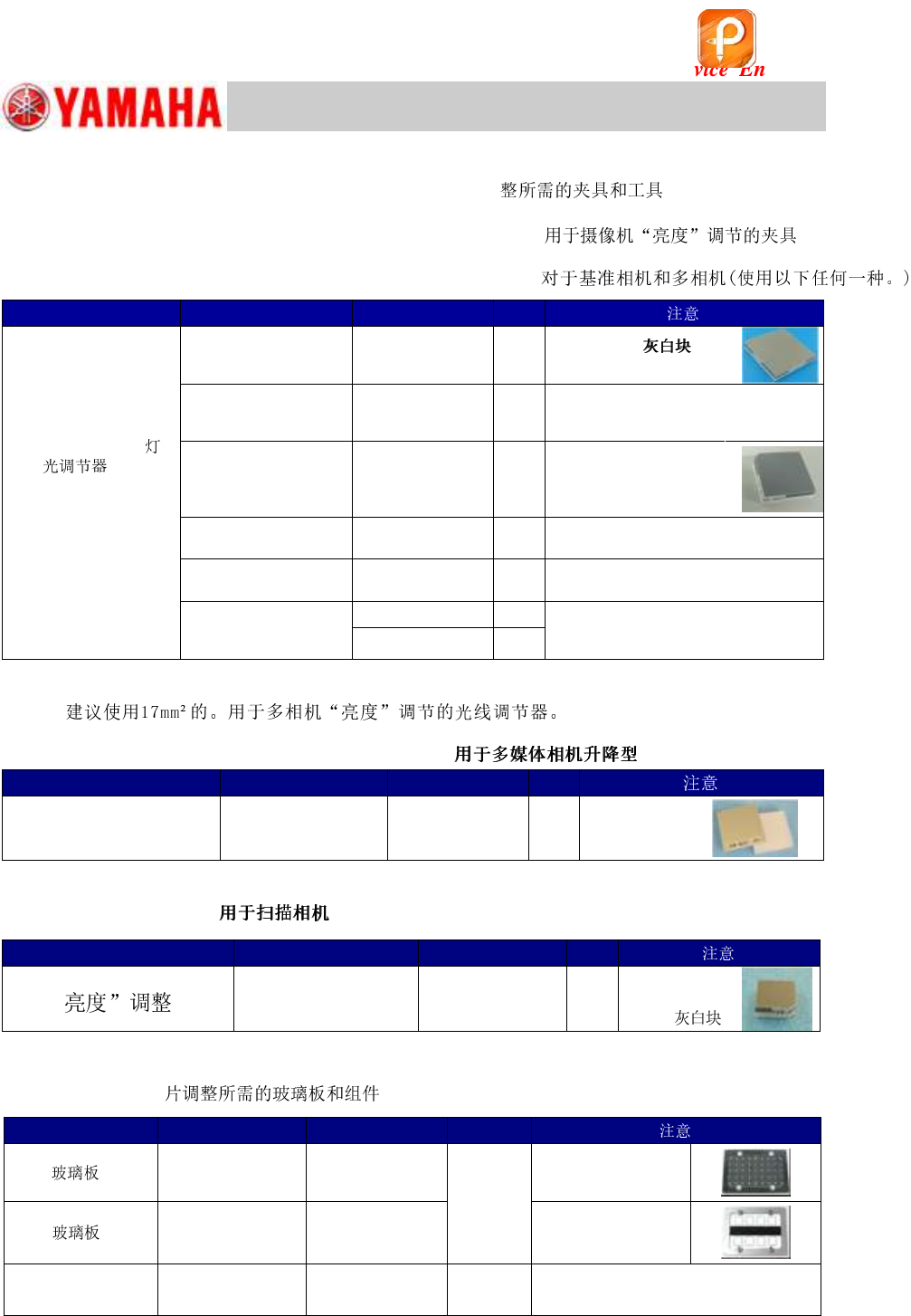
2. Jigs and tools required for the adjustment
2.1 Jigs for the “Lightness” adjustment of the cameras
For the Fiducial & Multi cameras (Use any of the following.)
Item
Part Name
Part No.
Qty
Light adjuster
(For the “Lightness”
adjustment of the
Fiducial camera and
the Multi camera)
LIGHT ADJ. 3 ASSY
LIGHT ADJ. 3 ASSY.
KHW-M8806-Cx
KMC-M8806-C0
1
35mm sq.
Light gray & White
LIGHT ADJ. 1 ASSY
LIGHT ADJ. 1 ASSY.
KHW-M8806-Ax
KMC-M8806-A0
1
35mm sq.
Dark and light gray & white, with
one chamfered corner
LIGHT ADJ. S ASSY
LIGHT ADJ. S ASSY.
KHW-M8806-Bx
KMC-M8806-B0
1
17mm sq.
Light gray & white,
with one chamfered
corner
LIGHT ADJUSTER S
KGT-M8806-0x
1
17mm sq.
Light gray & white
LIGHT ADJUSTER
KM1-M8806-00
1
35mm sq.
Dark and light gray & white
LIGHT ADJUSTER 1
KM1-M8806-10
1
35mm sq.
Dark and light gray & white, with a
3 hole
KM1-M8806-11
1
Table 2
* It is recommended to use a 17mm sq. light adjuster for the “Lightness” adjustment of the Multi
camera.
For the multi camera (Elevator type “Side” light)
Item
Part Name
Part No.
Qty
32mm sq.
Milky white light adjuster
LIGHT ADJ.4 ASSY
KHW-M8807-00
1
With silver
film
Table 3
For the Scan camera
Item
Part Name
Part No.
Qty
@
モ
LIGHT ADJ. 4 ASSY
KHW-M8806-D0
1
11mm sq.
Light gray &
White
LIGHT ADJ. 4 ASSY.
KMC-M8806-D0
Table 4
2.2 board and components required for the ACP-Chip
adjustmentACP
Table 5
Item
Part Name
Part No.
Qty
ACP
PCB
ASSY.4
KM0-M8810-40
1
(Select
either of
the two)
Double-faced tape:
20mm width
AMF
PCB
ASSY.1
KM0-M8810-10
Double-faced tape:
35mm width
1005 」ィゥー
REEL CERAMIC
1005
KGA-M880C-10
1
()
该文档是极速PDF编辑器生成,
如果想去掉该提示,请访问并下载:
http://www.jisupdfeditor.com/