00198608-02_SM_CP20P2_Kunde_EN.pdf - 第13页
3 Component camera, Z axis and component sensor 3.1 Replacing the Component Camera Service Manual SIPLACE SpeedStar (C&P20 P2) 01/2019 13 3 Component camera, Z axis and component sensor 3.1 Replacing the Component Ca…

2 Overview of the Modules
2.2 Overview of torques and tools required
12 Service Manual SIPLACE SpeedStar (C&P20 P2) 01/2019
2.2 Overview of torques and tools required
T07 03078400-xx Torque Screwdriver ESD 1.0-5.0 Nm
T44 00386132-xx Torque screwdriver ESD 0.1-0,6 Nm
T47 00386253-xx Torque screwdriver ESD 0.4-1.0 Nm
T08 03078706-xx Bitholder f. Screwdriver TorqueVario
T09 03073256-xx Extension / straight TX20
T76 00386135-xx Torque interchangeable blades 1.5 mm, hexagonal
T77 00386136-xx Torque interchangeable blades 2 mm, hexagonal
T78 03090019-xx Torque interchangeable blades 2.5 mm, hexagonal
T96 03171858-xx Torque Allen swap blade 1.5 mm TX6
T97 03075862-xx Torque Allen swap blade 1.5 mm TX8
T98 03171857-xx Torque Allen swap blade 1.5 mm TX10
T99 03171856-xx Torque Allen swap blade 1.5 mm TX20
Torques
Values in [Nm] T07 T44 T47 T08 T09 T76 T77 T78 T96 T97 T98 T99
Supplied with HMK X X X X X X X X X X X X
Supplied with HEK X X X X
Head assembly 2.70 X X
Component camera 1.30 X
Z cover (TX10) 1.30 X
Z cover (TX8) 0.70 X
Component sensor 1.90 X
DP linear guides 0.20 X
DP board clamping plates 0.10 X
PRV 0.90 X
Support plate (on PRV,
H-shaped)
0.60 X
Aperture ring 1.30 X
Aperture ring cover 1.30 X
Return unit fixtures 1.30 X
Return unit cylinder 0.65 X
Return unit driver 1.15 X
Holding circuit board (back
screw)
0.20 X
Holding circuit board (front
screw)
0.60 X
Screwed joint cover 0.30 X
Screwed joint 0.56 X
Screwed joint strands 0.35 X
Handle (top screws) 1.30 X
Handle (bottom screws) 4.00 X
Mount-retaining elements
(fixture from behind)
0.20 X
Mount (for mount-retaining
element, top left)
0.60 X
Fan 0.35 X
3 Component camera, Z axis and component sensor
3.1 Replacing the Component Camera
Service Manual SIPLACE SpeedStar (C&P20 P2) 01/2019 13
3 Component camera, Z axis and component
sensor
3.1 Replacing the Component Camera
Parts
Fig.4: Component camera type 48
03131695‑xx Component camera C&P (type 48) 8x8 GigE
For information about other cameras, please refer to the catalog of parts
Equipment and tools
T07 03078400-xx Torque Screwdriver ESD 1.0-5.0 Nm
T19 00318673-xx Wire cutter electronic size 110
T78 03090019-xx Torque interchangeable blades 2.5 mm, hexagonal
C08 00308458-xx Cable ties B=2.5mm, L=102mm Panduit
T --- Tools for removing/fitting and calibrating the placement head, if needed
(see also the service manual for your machine)
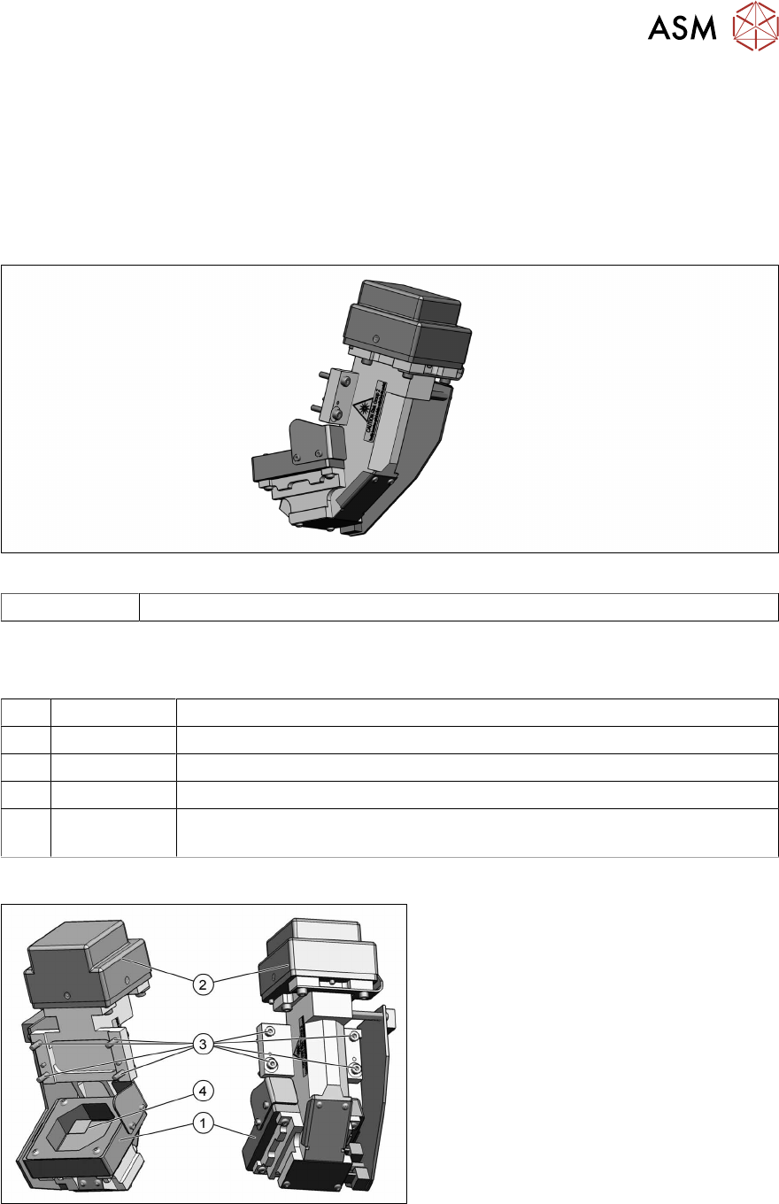
Overview
Fig.5: Component camera (type 48)
1. Component camera
2. Camera amplifier CCD
3. Four fastening screws (Allen 2.5) for
the camera on the head housing
ISO4762-M3x16-A2-70 [03042545‑xx]
4. Camera lens system
For further information about the repairs
needed, refer to section 3.1 "Replacing the
Component Camera" [}13].
3 Component camera, Z axis and component sensor
3.1 Replacing the Component Camera
14 Service Manual SIPLACE SpeedStar (C&P20 P2) 01/2019
Preparation
► Remove the head from the machine. For details about removing and fitting the placement
head, refer to the service manual for your machine.
Fit the head on the head mount [03056231‑xx].
CAUTION
Do not damage or contaminate the camera lens system.
► Make sure that you do not damage or contaminate the camera lens system.
► Make sure that the component sensor protective cap is fitted.
1.1.3 "Safety instructions for the component sensor" [}6]
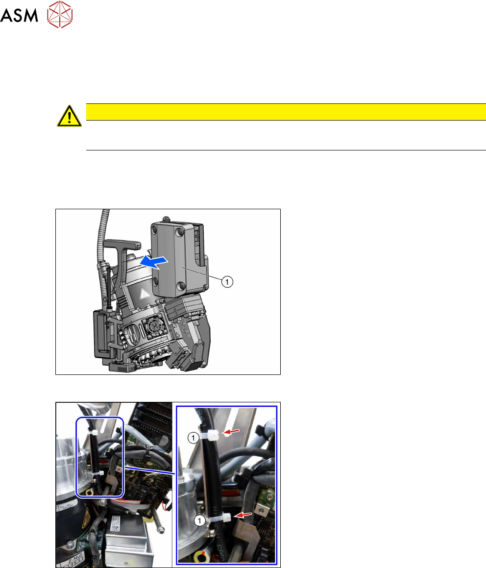
Removal
Fig.6: Pulling the cover off
► Pull the cover(1) off the intermediate
distributor.
The cover is fixed by four press studs
on the stay bolts.
Fig.7: Camera cable
► Loosen the cable ties(1).