00198608-02_SM_CP20P2_Kunde_EN.pdf - 第16页
3 Component camera, Z axis and component sensor 3.1 Replacing the Component Camera 16 Service Manual SIPLACE SpeedStar (C&P20 P2) 01/2019 3.1.1 Board: Vision LED controller VLC48 03146613-xx Vision LED controller VLC…
3 Component camera, Z axis and component sensor
3.1 Replacing the Component Camera
Service Manual SIPLACE SpeedStar (C&P20 P2) 01/2019 15
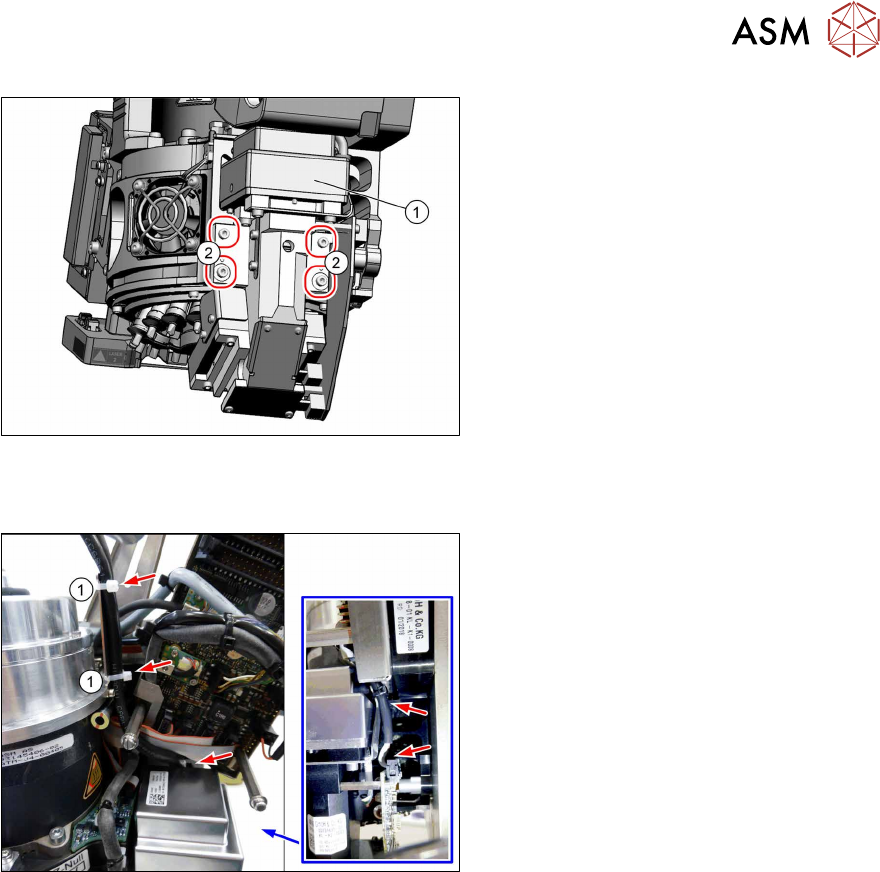
Fig.8: Screws fastening the component camera
► Remove the four fastening screws(2)
(Allen 2.5).
► Carefully pull the component camera
(1) off the locating pins.
Installation
Fig.9: Cables
► Fit the new component camera with
four screws (Allen 2.5, M3x16, torque
1.3Nm).
► Pay attention to how the cables are run
and fasten them with cable ties(1).
► Follow the removal instructions in reverse order for further installation.
► Calibrate the placement head after installation.
If this is not the case, brief calibration will not be suggested and standard calibration must be
performed.
3 Component camera, Z axis and component sensor
3.1 Replacing the Component Camera
16 Service Manual SIPLACE SpeedStar (C&P20 P2) 01/2019
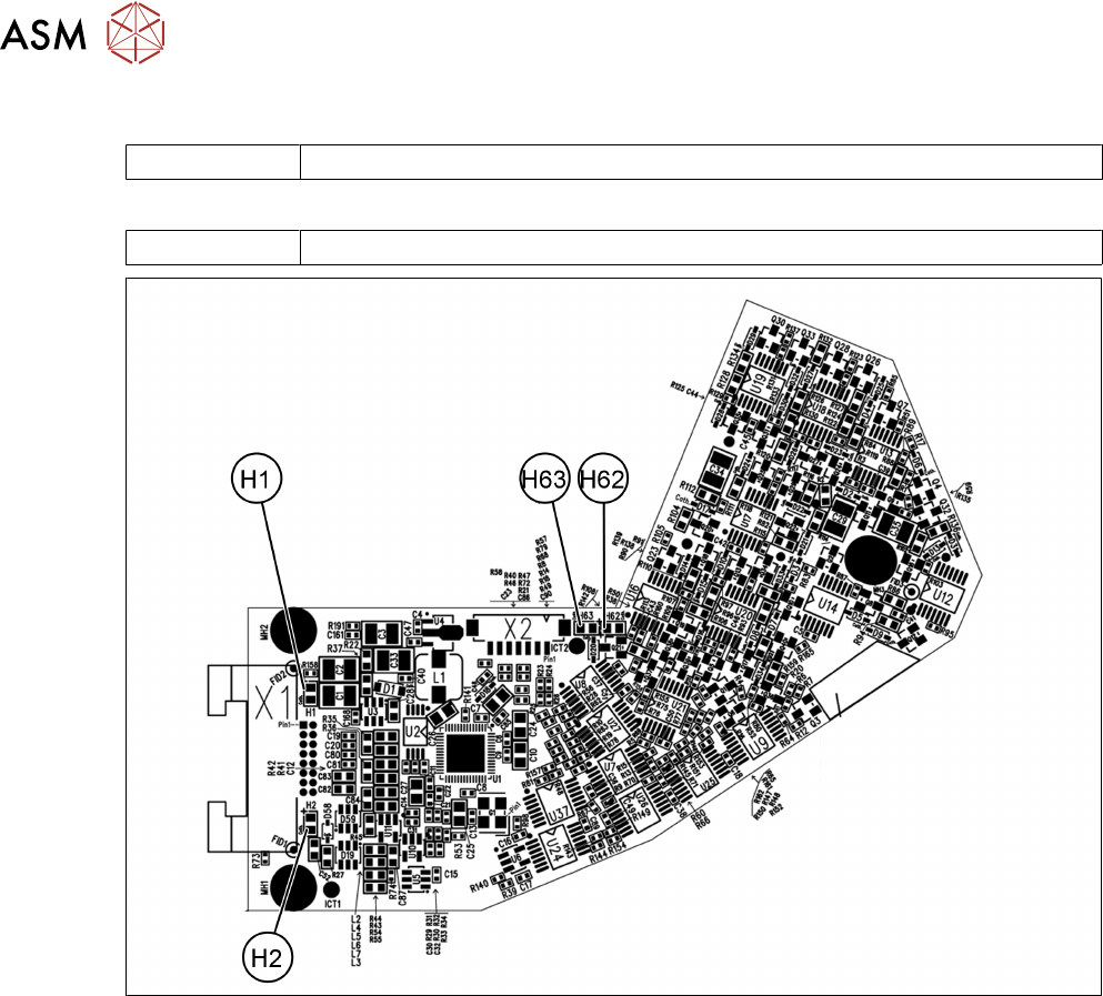
3.1.1 Board: Vision LED controller VLC48
03146613-xx Vision LED controller VLC48
This circuit board is fitted in the following component cameras:
03131695‑xx Component camera C&P (type 48) 8x8 GigE
Fig.10: Camera type 48 – board front
3 Component camera, Z axis and component sensor
3.1 Replacing the Component Camera
Service Manual SIPLACE SpeedStar (C&P20 P2) 01/2019 17
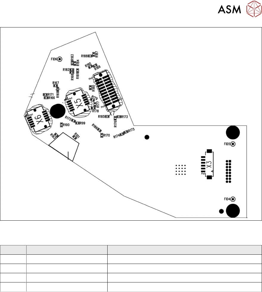
Fig.11: Camera type 48 – board back
LEDs [03146613-02]
LED Color Description
H1 Green 24V
H2 Green 42V
H62 Red Error
H63 Green, flashes Run