00196642-01 - AI BE-Kamera 38 CPP_de_en.pdf - 第20页
6 Assembly Assembly Instruction SIPLACE X Series Edition 09/2009 20 X Carefully lift the head out of the locating pins on the hea d plate. X If the head moun t [030562 31-xx ] is at hand, fix the placement head onto the …
Assembly Instruction 6 Assembly
Edition 09/2009
19
6.2 Dismantling the Placement Head
6
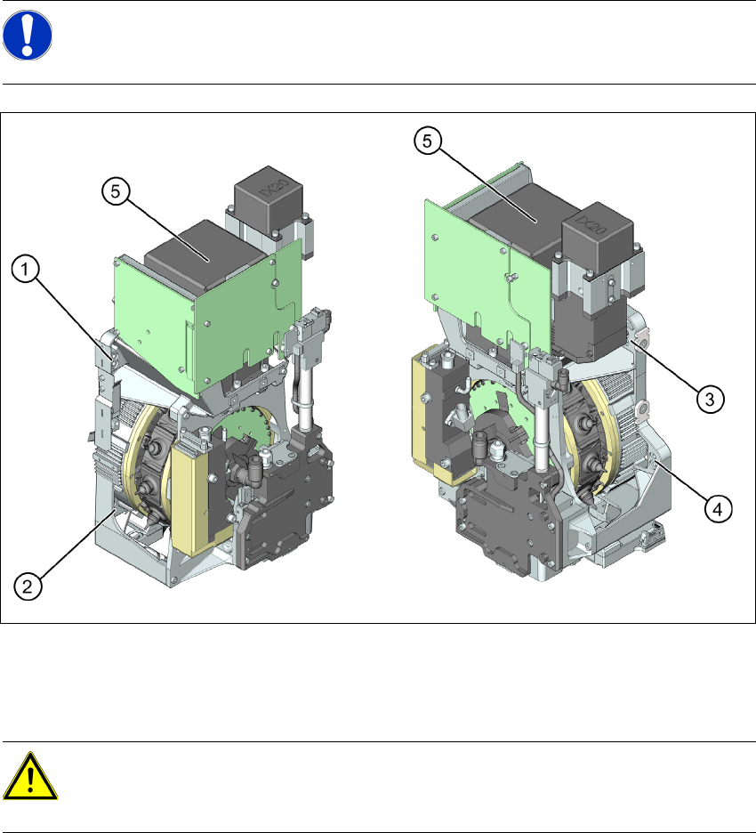
Fig. 6.2.1 Dismantling the placement head - view from the right and the left
1 to 4: Fixture holes (two each, depends on installation height).
5: Component camera
X Disconnect the pneumatic connection from the placement head.
X Disconnect the flat ribbon cable from the placement head (intermediate distributor).
X Loosen the screws fastening the strain relief on the component camera cable and carefully
unplug the cable. While unplugging the cable, press the clamps on both sides of the
connector.
X Loosen all four fastening screws with a long Torx screwdriver.
NOTE:
For further information on exchanging the placement head please refer to the Service
Manual of the relevant machine.
CAUTION: Take great care when dismantling the placement head!!
The component sensor prisms, underneath the placement head, could be damaged.
X Never place the CPP head down on the component sensor.
6 Assembly Assembly Instruction SIPLACE X Series
Edition 09/2009
20
X Carefully lift the head out of the locating pins on the head plate.
X If the head mount [03056231-xx] is at hand, fix the placement head onto the head mount.
6.3 Exchanging the Component Camera
6
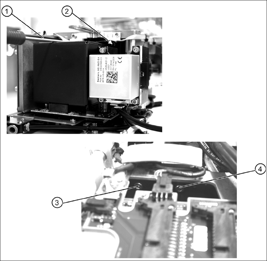
Fig. 6.3.1 Removing the component camera - fixation at the CPP head
X Remove the four fastening screws (items 1 to 4) of the component camera.
Assembly Instruction 6 Assembly
Edition 09/2009
21
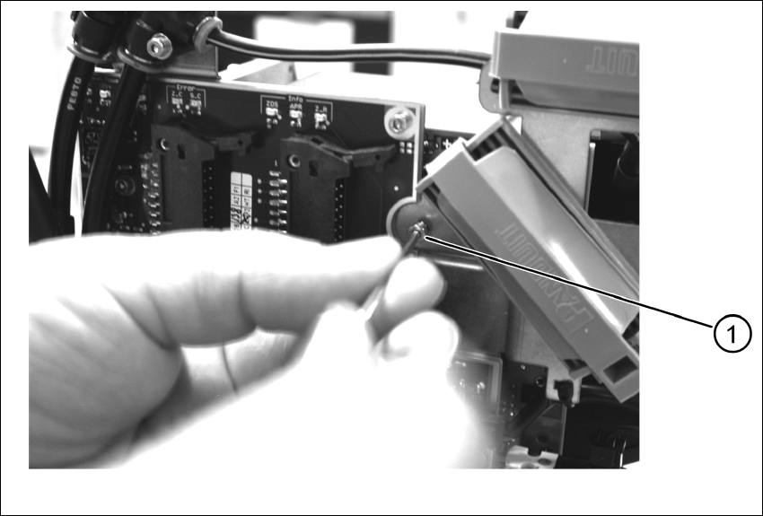
In addition to the four screws (M4), the component camera is fixed to the intermediate distributor
with an M 2.5 x 4 screw. 6
6
Fig. 6.3.2 Dismantling the placement head - safety screw
X Remove the safety screw (1).
X Carefully lift off the component camera.