00196430-0102-AI_Head_Reconfiguration_Kit_SX_CPP_en_de.pdf - 第74页
Installing the CPP Placement Head Assembly of the CPP Placement Hea d Height Adjustment and Install ation of the Nozzle Station 74 Assembly Instructions / Montageanleitung Head Reconfiguratio n Kit CPP Installing/Removin…
Installing the CPP Placement Head
Height Adjustment and Installation of the Nozzle Station Assembly of the CPP Placement Head
Assembly Instructions / Montageanleitung Head Reconfiguration Kit CPP 73
Installing/Removing Downholder
Installing/Removing Downholder
Installing downholder
Removing downholder
When exchanging the placement head type it may be necessary, depending on the new configuration,
to remove downholders and reject bins and replace them by coding sheets on unopccupied bin locations.
The configurations with reject bins, downholders and coding sheets are described in the relevant assem
-
bly instructions ([00196429--xx] for changeover to C&P20A, [00196430-xx] for changeover to CPP and
[00196431--xx] changeover to TwinHead).
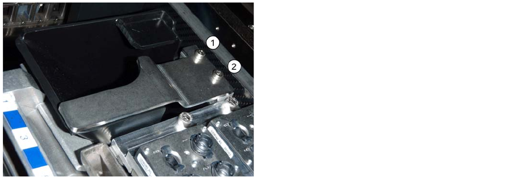
► Remove the two screws (1 and 2) and lift off the downholder.
► Remove the reject bin.
See also
3.4.7.3.3 Installing/Removing Coding Sheet [ ➙ 74]
Installing/Removing Coding Sheet
► Insert the reject bin [03063238-xx].
► Fasten the downholder [03079173-xx] directly on the
cast part of the used tape channel using two screws
(1 and 2).
No shim plates are required.
Installing the CPP Placement Head
Assembly of the CPP Placement Head Height Adjustment and Installation of the Nozzle Station
74 Assembly Instructions / Montageanleitung Head Reconfiguration Kit CPP
Installing/Removing Coding Sheet
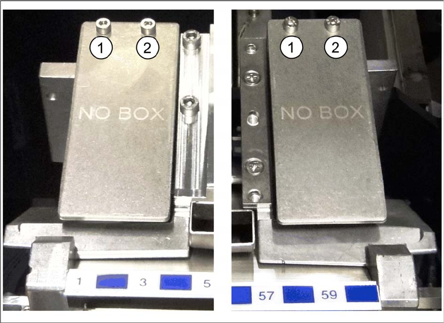
Coding sheets are used on unoccupied bin locations.
Installing coding sheet
Coding sheet left and right
► Fasten the coding sheet [03083883-xx] directly on cast part of the used tape channel using two
screws (1 and 2).
No shim plates are required.
Removing coding sheet
When exchanging the placement head type it may be necessary, depending on the new configuration,
to remove downholders and reject bins and replace them by coding sheets on unopccupied bin locations.
The configurations with reject bins, downholders and coding sheets are described in the relevant assem
-
bly instructions ([00196429--xx] for changeover to C&P20A, [00196430-xx] for changeover to CPP and
[00196431--xx] changeover to TwinHead).
► Remove the two screws (1 and 2) and lift off the coding sheet.
Installing the CPP Placement Head
Connections on the Hotlink Card (Box PC) Installation and Removal of Options
Assembly Instructions / Montageanleitung Head Reconfiguration Kit CPP 75
Connecti ons on the Hotlink Card (B ox PC)
3.4.8 Connections on the Hotlink Card (Box PC)
► Insert a USB stick or another appropriate storage medium into the USB slot of the station computer.
► Save the machine data from the storage medium to the station computer.
Installation and Removal of Options
3.5 Installation and Removal of Options
Option Nozzle Changer
3.5.1 Option Nozzle Changer
► When replacing the TwinHead by a C&P20A/CPP head the nozzle changer of the TwinHead must
be replaced by the appropriate nozzle changer for the C&P20A/CPP head.
► For installing and removing the nozzle changer please refer to the Assemby Instruction "Nozzle
Changer SX1/2" [00196432-xx].
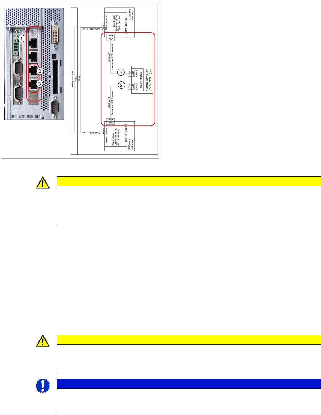
Connections on the hotlink card
Legend
1. Hotlink connections CAM 0 to CAM 3 at the BOX PC.
2. CAM 2 - X2pr
03055214: stationary IC / FC camera 1
3. CAM 3 - X3pr
03055211: stationary IC / FC camera 2
► Plug in the Hotlink cable for the relevant component
camera.
CAUTION
The Hotlink cables of the IC and FC cameras must be unplugged for the placement area in
which there is a C&P20A or a CPP head if no stationary camera is used here.
Do not connect the Hotlink cables which are not in use!
Do not confuse the Hotlink cables with the twisted pair cables!
CAUTION
Crash danger
Operate a placement head with its appropriate nozzle changer only. There is crash danger
when using a wrong nozzle changer.
NOTICE
If a second nozzle changer row is retrofitted, it may be necessary to loosen the COT insert and
move it outwards. Read the applicable service manual for this. After completion of work, this
needs to be fixed into place again and all attached parts (nozzle changer) must be remeasured.