Manuelles Tray an D1 an Stellplatz 2.pdf - 第16页
2 Assembly instructions Special design for manual tray at lo cation 2 SIPLACE D1 Special Design 05/2007 Edition 16 2.3 Restrictions The maximum co nveyor width is approxima tely 260 mm. 2 The tray holder is intend ed sol…
Special Design 2 Assembly instructions Special design for manual tray at location 2 SIPLACE D1
05/2007 Edition
15
2 Assembly instructions
Special design for manual tray at
location 2 SIPLACE D1
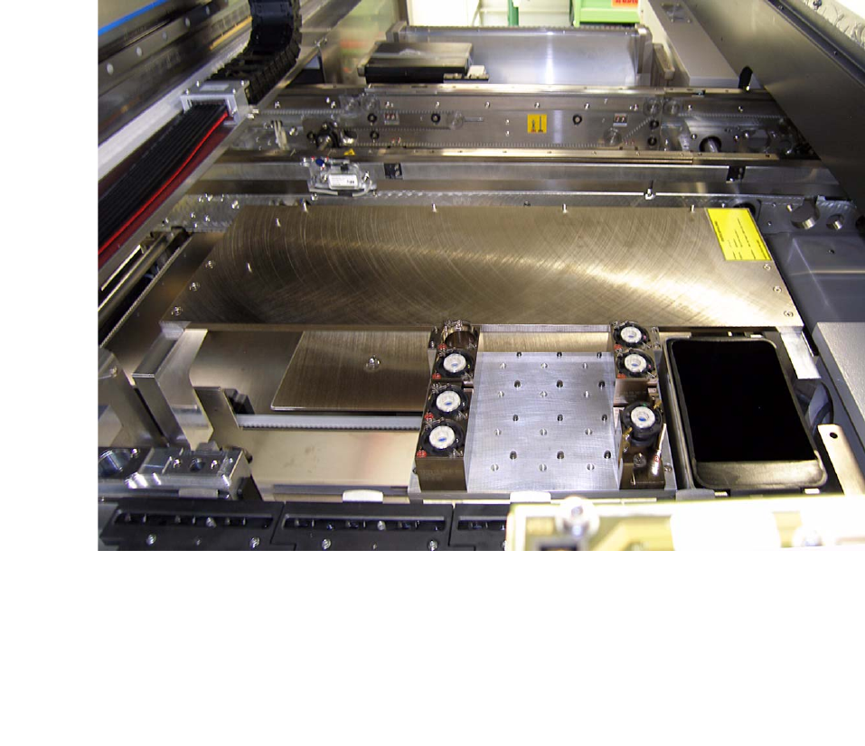
2.1 Working principle
At SIPLACE D1 it is possible to place a JEDEC Tray inside the machine. 2
2
2
2.2 Requirements
2
Hardware: SIPLACE D1 - single conveyor
Software: -

2 Assembly instructions Special design for manual tray at location 2 SIPLACE D1 Special Design
05/2007 Edition
16
2.3 Restrictions
The maximum conveyor width is approximately 260 mm. 2
The tray holder is intended solely for components which, including the tray, do not exceed 16 mm
in height. 2
If other components are to be placed in this tray holder, they must not be higher, otherwise there
is a risk of crashing with the placement head. 2
If a service tool is used, the machine must be set up with the standard setup once more. 2
Only a limited performance calculation is possible. 2
2
The restrictions concerning the component range still apply. 2
2
2.4 Scope of delivery
– Tray holder for location 2 (for 1 JEDEC Tray)
– 2 hexagon socket head screws M5 X 30 mm for tray holder
– Fixing bracket for limit switch
– 2 magnets for fixing the tray
– SOKO adhesive label
– Programming guide for arbitrary carrier under SIPLACE Pro (00194607-xx)
– Assembly instructions for tray holder SIPLACE D1 (00195627-xx).
2.5 Tools and consumables required
– Set of hexagon socket spanners
– Set of screw drivers
– Cable ties
– Self-adhesive cable clamps
–Side cutters
– Ethyl alocohol for cleaning
– Lint-free cloths.

Special Design 2 Assembly instructions Special design for manual tray at location 2 SIPLACE D1
05/2007 Edition
17
2.6 Safety instructions
WARNING
The safety instructions from the “Operational safety” chapter of the user manual and servicing in-
structions take precedence over these instructions. 2
The SIPLACE placement machines are supplied with main power voltage.
Consequently parts of these systems carry dangerous voltages! This voltage is present at certain
modules inside the machine base, even when the machine is switched off at the main power
switch.
Incorrect handling of the placement machine or touching live parts of the machine can result in
death or severe injury, and considerable damage to equipment.
BEFORE starting any work, shut down the operating system correctly, then switch the machine
OFF at the main power switch and disconnect from the main power supply. In addition, the com-
pressed air supply must be switched off at the compressed air unit's main valve in the machine
base and vented by actuating the needle valve on the compressed air unit.
There is DANGER for heart pacemaker wearers in the vicinity of the linear motors, as described
in detail in the "Special safety instructions for working in the vicinity of strong magnetic fields"
section of the user manual and service manual.
Always follow the accident prevention regulations, DIN or other standards and special safety
rules applicable in your country.
Pay attention to the information concerning residual voltages in the Operational Safety chapter.
Follow the ESD regulations as described in the operational safety section of the operating
instructions.
During the retrofit, always secure the machine to prevent access by other people and to prevent
it being switched on again. The procedure is described in the “Locking the machine…” section of
the user manual.
Working with the SITEST program further increases the risk of accident.
The SITEST program must only be used by authorized and trained personnel.
2
2.6.1 Definitions
2
Please note 2
2
2
2