00192286-03.pdf - 第18页
1 Service manual Linear motor, secondary part SIPL ACE HS-50 Linear motor, secondary part, HS-50 1.3 Magnets with cover sheet 02/2009 Edition 18 1.3 Magnet s with cover sheet 1.3.1 Required p art s Item number of the ret…
Linear motor, secondary part, HS-50 1 Service manual Linear motor, secondary part SIPLACE HS-50
02/2009 Edition 1.2 Safety instructions
17
1.2.2 Safety instructions on magnetism
1
1
RISK TO HEART PACE-MAKER WEARERS 1
1
CAUTION POWERFUL MAGNETIC FIELD 1
1
WARNING RISC OF CRUSHING 1
: Do not approach permanent magnets when carrying metal objects made of iron, steel or nickel.
The powerful force of attraction may cause fingers to be crushed.
1
: The permanent magnets of the y axis have an extremely powerful magnetic field.
Personnel wearing heart pace-makers are NOT permitted to stand in the vicinity of
permanent magnets.
: Do not wear watches in the vicinity of permanent magnets since they can be dam-
aged.
: Do not bring magnetic data media, check or credit cards near permanent magnets -
the data on the data media may be erased by the magnetic field of the permanent
magnets.
1 Service manual Linear motor, secondary part SIPLACE HS-50 Linear motor, secondary part, HS-50
1.3 Magnets with cover sheet 02/2009 Edition
18
1.3 Magnets with cover sheet
1.3.1 Required parts
Item number of the retrofit kit: 00357143-01 1
The retrofit kit consists of: 1
– magnets with foil, 128 mm unit item no.:. 00355752-01 1 piece
– magnets with foil, 512 mm unit item no.: 00355754-01 3 pieces
– cover sheet item no.:. 00355786-01 1 piece
– supporting rail item no.: 00355787-01 1 pieces
– service manual linear motor sec. part HS-50 item no.:. 00192286-01 1 piece
– removal tool magnets (HS-50) item no.:. 00358519-01 1 piece
1
1
Linear motor, secondary part, HS-50 1 Service manual Linear motor, secondary part SIPLACE HS-50
02/2009 Edition 1.4 Assembly of magnets with cover sheet
19
1.4 Assembly of magnets with cover sheet
Assembly order 1
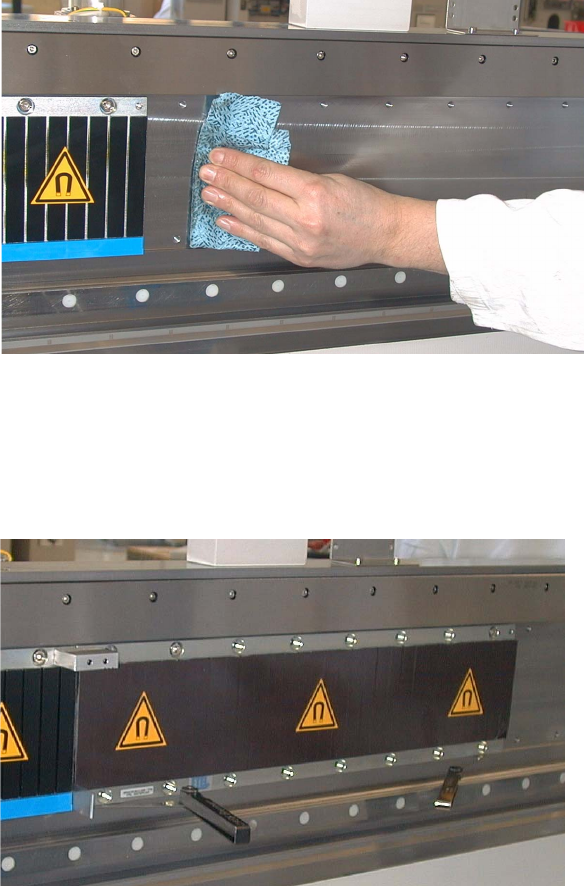
: Fit the magnetic plates on one side of the placement machine.
Start on one side with the middle plate, then fit the plate to the left of it, then the plate to the
right and finally the small plate on the far right.
Assembly sequence 1
: Move both gantries as far as they will go to the right.
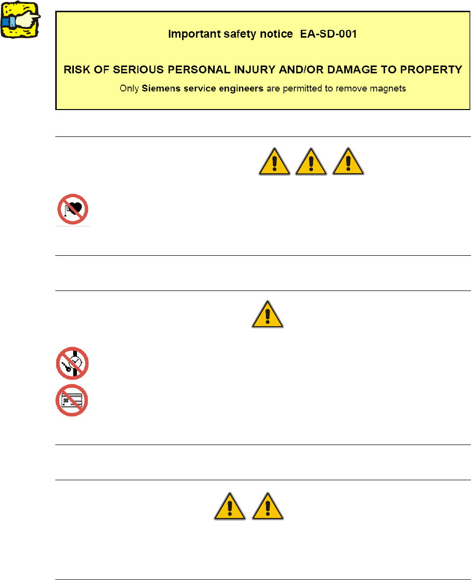
: Use a dry cloth to wipe the surface to which the magnetic plates are to be screwed.
1
1
: Hold the middle magnetic plate against the corresponding holes in the machine’s base frame.
Place two 1 mm thick feeler gauges beneath the magnetic plate so that the holes line up ex-
actly with the screw.
1