OperationInstruction_Vsision XP.pdf - 第189页
V ISION XP+ V AC Page 181 7 Alarm Messages 7.5 Cooling section open (VXP) Operating Instructions V ersion 1.5 7.5 Coolin g section open (VXP ) The cover at the cooling section or condensation trap is open or not locked. …
Page 180 VISION XP+ VAC
7 Alarm Messages
7.4 Frequency Converter
Operating Instructions
Version 1.5
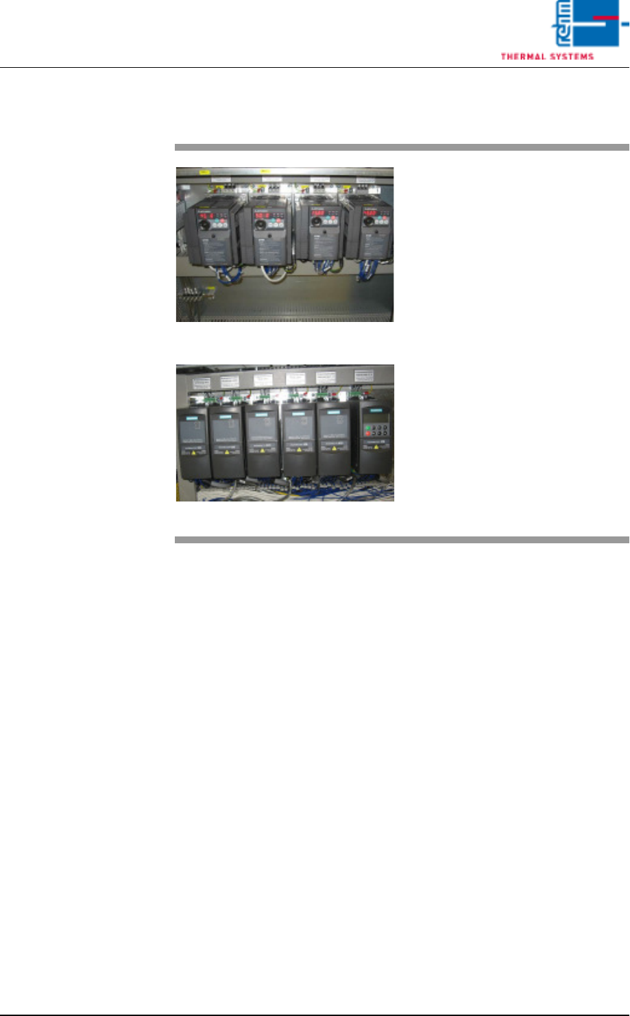
7.4 Frequency Converter
Fig. 7-6 Frequency Converter
Fig. 7-7 Frequency Converter by Siemens
A frequency converter has triggered
the error message.
Procedure:
• Check the frequency converter in
the control cabinet.
• Inspect the fuse.
• Determine the fan defect of the
heating or the cooling zone.
• Control the fans (whether they are
dirty).
• Reset the frequency converter.
Refer to the included frequency
converter operating instructions
to this end.
VISION XP+ VAC Page 181
7 Alarm Messages
7.5 Cooling section open (VXP)
Operating Instructions
Version 1.5
7.5 Cooling section open (VXP)
The cover at the cooling section or condensation trap is open or not locked.
Procedure:
• Close the cover or lock it
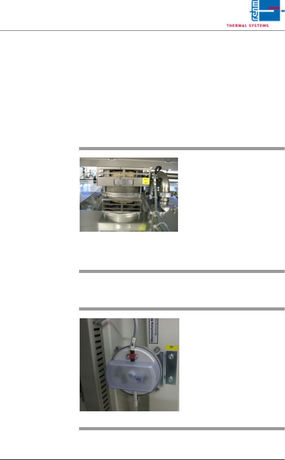
7.6 Fan Monitoring (option)
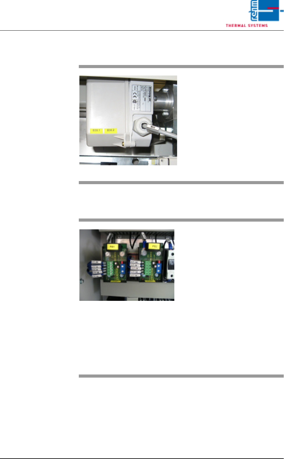
7.7 Exhaust
Fig. 7-8 Fans
A heater fan has fallen short of the
minimum speed in RPM selected in
the software.
Procedure:
• Check the fan monitoring window
in order to determine which fan is
effected (see also chapter 5.5.12
Fan Monitoring (optional), on
page 125).
• Check the connection of the ef-
fected fan.
• Clean or replace the fan.
Fig. 7-9 Exhaust Underpressure Capsule
The exhaust system has triggered
an error message because exhaust
volume is too low.
Procedure:
• Clean the exhaust ducts.
• Switch on or repair the plant ex-
haust system.
• Check the setting at the under-
pressure capsule.
Page 182 VISION XP+ VAC
7 Alarm Messages
7.8 Process Chamber Open
Operating Instructions
Version 1.5
7.8 Process Chamber Open
7.9 Heating Elements Fault
Fig. 7-10 Lifting Motor Limit Switch
The process chamber is not fully
closed.
Procedure:
• Inspect the closing edges for pos-
sible foreign objects.
• Click the software button used to
close the process chamber once
again.
• Make sure that the signal from the
safety switch arrives at the digital
input.
Fig. 7-11 Current monitoring module
In the heating zones, pyrolysis tube
heating flows to a low or no current.
Possible causes:
• Green LED flashes: the set value
is reached.
• Orange LED: Power shift value
has fallen below limit.
• Red LED: power limit has been
exceeded for more than T ^.
Procedure
• Fuse tripped, measure heating
and replace if necessary.
• Fuse not tripped, readjust current
module. Strong mains fluctua-
tions.