OperationInstruction_Vsision XP.pdf - 第191页
V ISION XP+ V AC Page 183 7 Alarm Messages 7.10 Overtemperature Protection T ripped (Option) Operating Instructions V ersion 1.5 7.10 Overtem peratur e Protect ion T ripped (Op tion) 7.1 1 Driv e Motor The “Drive M otor”…
Page 182 VISION XP+ VAC
7 Alarm Messages
7.8 Process Chamber Open
Operating Instructions
Version 1.5
7.8 Process Chamber Open
7.9 Heating Elements Fault
Fig. 7-10 Lifting Motor Limit Switch
The process chamber is not fully
closed.
Procedure:
• Inspect the closing edges for pos-
sible foreign objects.
• Click the software button used to
close the process chamber once
again.
• Make sure that the signal from the
safety switch arrives at the digital
input.
Fig. 7-11 Current monitoring module
In the heating zones, pyrolysis tube
heating flows to a low or no current.
Possible causes:
• Green LED flashes: the set value
is reached.
• Orange LED: Power shift value
has fallen below limit.
• Red LED: power limit has been
exceeded for more than T ^.
Procedure
• Fuse tripped, measure heating
and replace if necessary.
• Fuse not tripped, readjust current
module. Strong mains fluctua-
tions.

VISION XP+ VAC Page 183
7 Alarm Messages
7.10 Overtemperature Protection Tripped (Option)
Operating Instructions
Version 1.5
7.10 Overtemperature Protection Tripped (Option)
7.11 Drive Motor
The “Drive Motor” alarm is displayed if the motor is overloaded. The mes-
sage is triggered by the temperature or the current monitoring function.
7.12 Condensate Trap Error (VXP)
Possible causes:
• The condensate trap fans are at a standstill.
• The frequency converter indicates an error.
• The lock is not correctly closed.
Procedure:
• Inspect the fans and repair if necessary.
• Inspect the frequency converter and repair if necessary.
Make sure that the lock is correctly closed.
The condensate trap can only be opened after activating the “unlock con-
densate trap” button, which is located in the main window. See item P in Fig.
5-11 Main Window, on page 85 in the “Software” section to this end. Beyond
this, the fans may not be running.
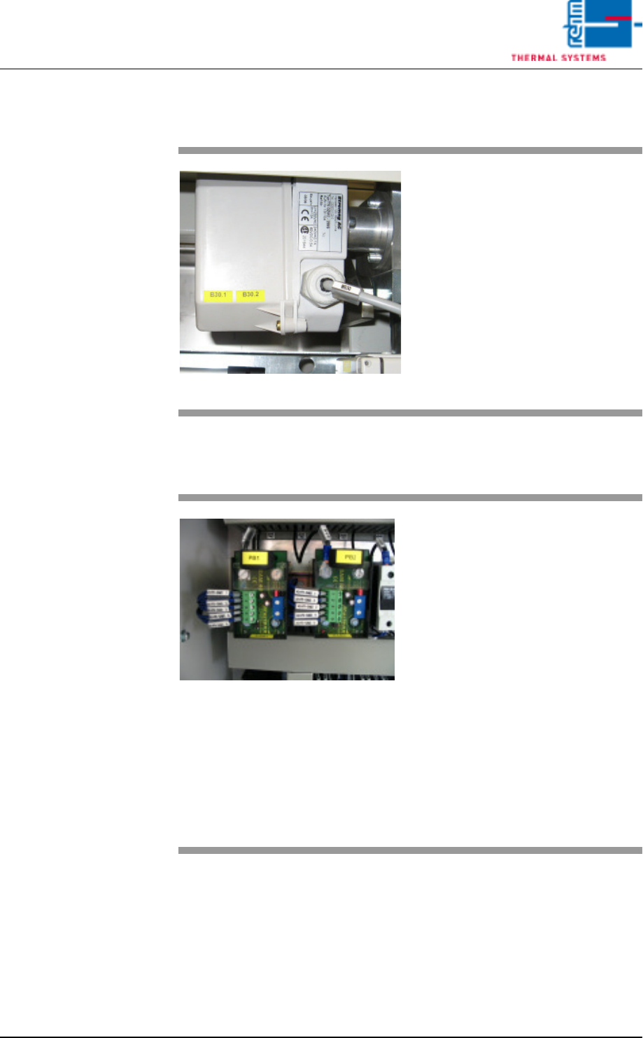
Fig. 7-12 Temperature Limiter
An additional overtemperature pro-
tector switch has been tripped. The
temperature has risen to above the
selected maximum temperature at
the temperature limiter in one of the
temperature zones.
Possible causes:
• Heat controls set incorrectly
• Overheated heating element
• Defective thermocouple
• Defective temperature limiter
Details regarding the temperature
limiter are included in chapter 4.14
Additional Heat Zone Monitoring
(optional), on page 78.
Page 184 VISION XP+ VAC
7 Alarm Messages
7.13 Power Supply
Operating Instructions
Version 1.5
After closing the condensate trap, it must be locked again with the same but-
ton. The fans do not start back up again until the condensate trap has been
locked.
If the „Condensate Trap Error“ alarm cannot be reset with the „Reset Alarm“
button, the system must first be switched to the service mode and the „Open
Condensate Trap“ button must be clicked. As a result, the condensate trap
fans are no longer activated.
If the „Open Condensate Trap“ button indicates that the fans are at a stand-
still („Stopped“), the lock can once again be secured with the help of the
„Open Condensate Trap“ button, and the fans can be operated again. „Run-
ning“ should then appear at the display and the alarm should be reset.
7.13 Power Supply
7.14 Cooling Tract Circulation
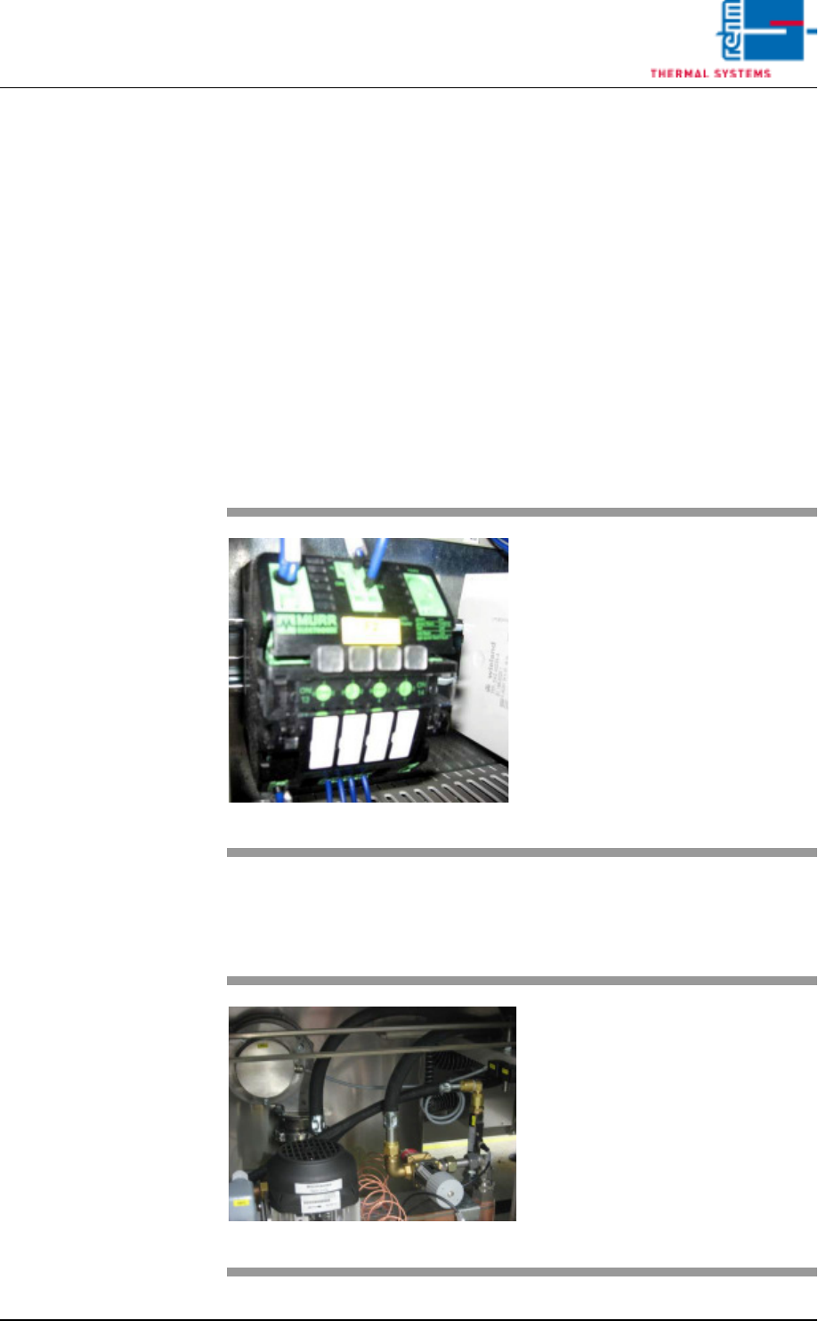
Fig. 7-13 Power Supply Fuse
The power supply alarm appears
when the fuse blows.
Procedure:
1. The triggered fuse is identified
by means of a red LED.
2. Press the red-shining button to
reset the error.
Fig. 7-14 Cooling tract circulation
The fan is supervised for recircula-
tion. If there are malfunctions, an
alarm will be released.