Hybridklemmung mit Vakuumabfrage (Funktionsbeschreibung).pdf - 第32页
F unctional description - Special design for the hybrid clamping unit with vacuum check 02/2006 Edition 32 2.3.7 Input belt stopper The stopper on the input belt ensures that it is a lways the first barcode in the wafer …
Functional description - Special design for the hybrid clamping unit with vacuum check
02/2006 Edition
31
2.3.4 Vacuum check
The placement process does not start unless three conditions are fulfilled: 2
– The vacuum threshold in the Keyence pressure sensor has been reached (approx. –650
mbar).
– The lifting table is "up".
– The center belt sensor is covered (photoelectric switch).
2.3.5 Deactivating the width adjustment unit
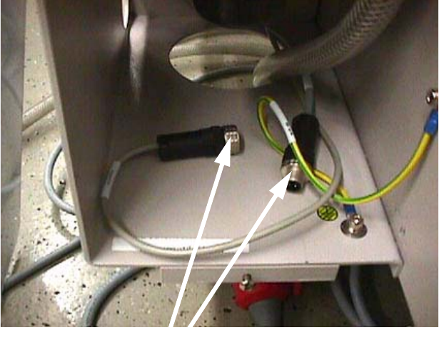
The conveyor side walls are prevented from moving together when the vacuum tooling / solenoid
valve connecting cable is plugged in. 2
2
2.3.6 Opticon barcode reader
Only the PCB barcode of the first substrate in the wafer boat has to be read. To guarantee this an
additional stopper is installed on the input belt. 2
2
2
2
2
Joining the connectors prevents the
conveyor side walls moving together.
Functional description - Special design for the hybrid clamping unit with vacuum check
02/2006 Edition
32
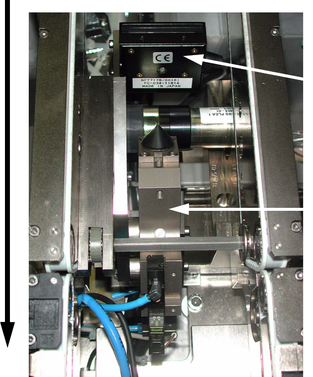
2.3.7 Input belt stopper
The stopper on the input belt ensures that it is always the first barcode in the wafer boat that is
read. It extends when the barcode reader is triggered and moves back in once the barcode has
been read (see picture). 2
2
2
2
2
2
2
2
Direction of PCB transport
Barcode scanner
Additional stopper
module on the input belt
Functional description - Special design for the hybrid clamping unit with vacuum check
02/2006 Edition
33
2.4 Parts required
2.4.1 Modules
PCB barcode distribution board (part no.: 00343635-01) 2
2
2
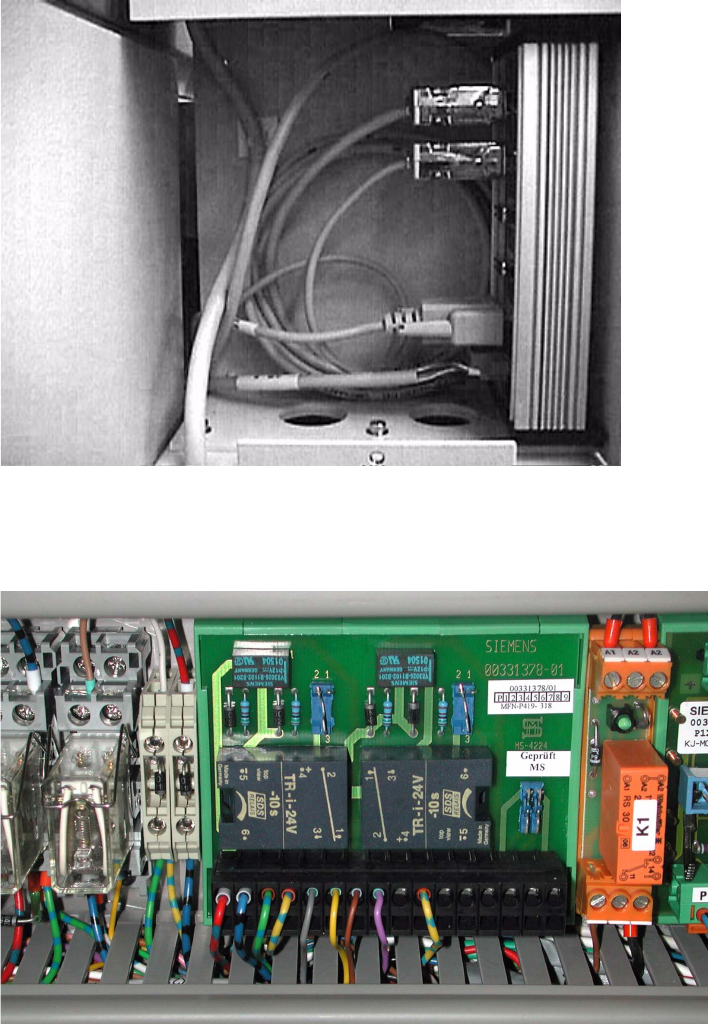
Vacuum tooling control (part no.: 00331378-01) 2
2
2