SM_SXDX12_intern_03-2017_en.pdf - 第34页
Service Work Y-guide carriage / Y-loose bearing Replace Final Work 34 Service Manual (Internal) SIPLACE SX1/SX2/DX1/DX2 2.6.4 Final Work ▪ Check the guide rails on scuf fs such as Chat termarks.If necess ary, replace the…
Service Work
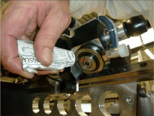
Exchange loose bearing running block LR205-2RSR [03076849-xx] Y-guide carriage / Y-loose bearing Replace
Service Manual (Internal) SIPLACE SX1/SX2/DX1/DX2 33
Check the guide rails on scuffs such as Chattermarks.If necessary, replace the guide rail. Please refer
to the chapter guide rails exchange in this internal service manual.
Mount the magnets as described in Chapter Magnets mount.
► Move the gantry as shown in the assembly gantry instructions SIP. SX1/SX2 [00196626-xx] section:
3.4 Installation of the gantry described back into the machine.
► Fix the cable chain with the hex spacers (these must be secured with Loctite 241. Plug all cables and
hoses again. For details, see also: Chapter: 3,5 trailing cable attach respectively service manuals
SX Chapter 3.3.12 Y-trailing cable exchange [03075584-xx]
► Mount the buffer and close the doors on the side. (The screws of the buffer with 14 Nm torque must
be tightened.
► Check the settings of the scanning head to the read head MS20.xxM / tester PG-U 03071361-xx
and set the Position possibly with the FEELER 0.75 mm plastic 03090774-xx as new.
► Calibrate the machine as shown in the assembly instructions gantry SIP. SX1/SX2 [00196626-xx]
chapter 3.6.6 perform calibration.
► Following calibration steps must be preformed:
1. Adjust encoder Y-axis
Travel range
3. Parameterization x-axis
4. Mapping Y-axis
Both sides with the thread lock marked in red locking var-
nish.
Fit the cover plate
Service Work
Y-guide carriage / Y-loose bearing Replace Final Work
34 Service Manual (Internal) SIPLACE SX1/SX2/DX1/DX2
2.6.4 Final Work
▪ Check the guide rails on scuffs such as Chattermarks.If necessary, replace the guide rail. Please
refer to the chapter guide rails exchange in this internal service manual.
▪ Mount the magnets as described in Chapter Magnets mount.
Drive the gantry as shown in the assembly instructions gantry modularity SIP. SX1/SX2 [00196626-xx]
Chapter: 3.4 Installation described the gantry back into the machine.
Fasten in place the cable chain with the hex spacers (this need with Loctite 241
secured. Unplug all cables and hoses again. For details, see also
under Chapter: 3.5 trailing cable attach respectively service manuals SX Chapter 3.3.12 Y-cable trailing
exchange [03075584-xx]
Installe the buffer again and close the lateral doors. (The bolt of the buffer
must be tightened with a torque of 14 Nm.
► Check the settings of the read head with the read head MS20.xxM / tester PG-U
03071361-xx and set the Position possibly with the FEELER 0.75 mm plastic 03090774-xx
new on.
► Calibrate the machine as shown in the assembly instructions gantry SIP. SX1/SX2
Perform [00196626-xx] section 3.6.6 calibration described.
The following actions will be carried out automatically:
1. Adjust encoder Y-axis
Travel range
3. Parameterization x-axis
4. Mapping Y-axis
Service Work
Final Work Replacement Y-Guide Rails
Service Manual (Internal) SIPLACE SX1/SX2/DX1/DX2 35
2.7 Replacement Y-Guide Rails
Tools required
1 x 03065307-xx Exccentric device Y-leadership, kpl.
1 x 00376625-xx Torque wrench with reversible ratchet
1 x 03065304-xx spacer for Y magnets
1 x 60519813-xx Gantry lift, SX1/2 CoD
SX1 - → 1 x 60519814-xx gantry tub, SX1 / 2 CoD
SX2:- → 2 x 60519814-xx Gantry tub, SX1/2 CoD
16 x 03097977-xx safety cover Y magnets SIPL.SX1
1 x 00375988-xx label: Warning of a magnetic field
1 x 00386029-xx label: Warning hand injuries
1 x 00386030-xx label warning for strong magnets
1 x 00195600-xx TI Safety note maglev, D + E
2 x 03097870-xx plastic wedge, 65 x 180mm
1 x 03097897-xx copper hammer, 750 g
Required spare parts
2 x 03077921 - guide rail MR S 25-154 (with red screw cap)
2 x 03083778 - guide rail MR S 25-1994 with red screw cap)
76 x 03068057 - ISO 4762 - M 5 x 25-12.9 geometric, 321 + VL.
Exchange guide rails
Lift preparation "2.2 Prepare Gantry lift" [ ➙ 16]
Preparing the Machine"2.3 Machine preparation" [ ➙ 16]
-Remove the magnets as described in "Replacing the magnets". "2.5 Exchange / Demounting of Y-Mag-
nets" [ ➙ 20]
Alternatively, the magnets can also remain in the machine and only with the cover be covered. But con-
sider the here still act magnetic forces and the rails should not come too close to them. Crushing.
Remove the gantrys as described by the gantry modularity
Disassembling guide rail
- Resolve the bolts of the guide rails and replace the guide rails through new ones. The new rails must
be mounted again in the same sequence and position.
Tighten all the bolts slightly and loosen them again with a half turn. The rails will be later pressed with
the excentric device Y leadership against the guide groove.
Now mount the magnets as described below under "Replacing the magnets".
Remove if required the spacer