Head PCB - Overview en.pdf - 第5页
Description of the Circuit Boards CP14 Vacuum Sensor Holdi ng Circuit Board CP14 Head PCB Overview Step by Step Analysis 5 DIP switch 1.3 1 . 3 V a c u u m S e n s o r H o ld in g C ir c u it B o a r d C P 1 4 Vacuum Sen…
Description of the Circuit Boards CP14
Intermediate Distributor Board CP14P
4 Head PCB Overview Step by Step Analysis
1.2
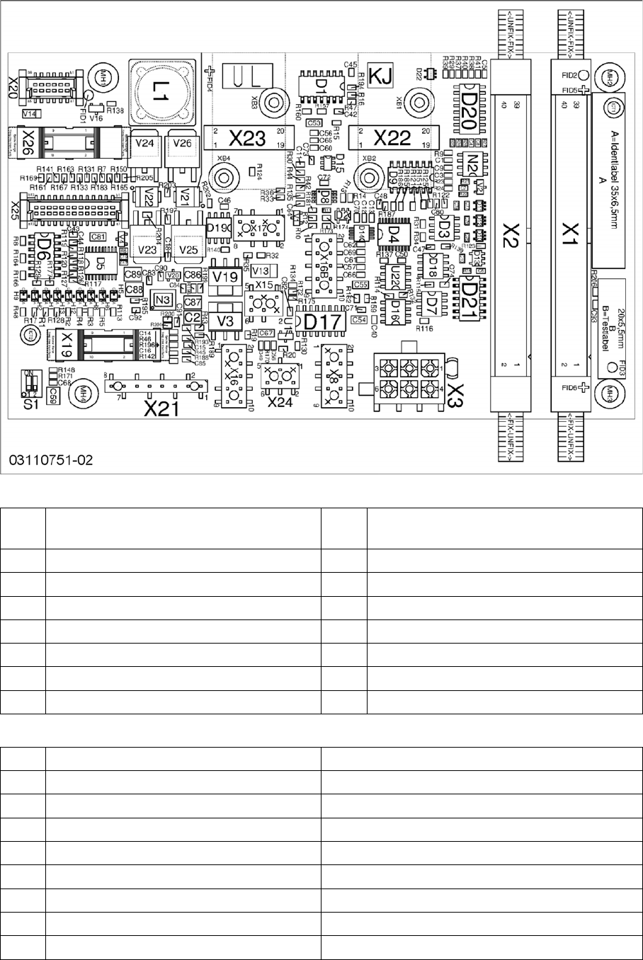
1.2 Intermediate Distributor Board CP14P
Intermediate Distributor Board CP14P
Connector
LEDs
X1, X
2
Flat ribbon cable to the head adapter X3 Power supply for star motor
X8 Power supply for Z axis X15 Valve for return unit
X16 CAN bus X16b CAN bus
X17 Z axis light barrier down X19 Board for holding circuit vacuum sensor
X20 Power supply for ED distributor X21 Diagnosis connector
X22 Incremental star X23 Incremental Z axis
X24 Fan X25 Digital pressure control valve
X26 Component sensor
H1 Fan Yellow
H2 Fan error Red
H5 +5V Green
H6 +15V Green
H8 +24 V Green
H9 Error 24 V DP Red
H11 24 V DP ON Yellow
H12 Return cylinder ON Yellow
H13 Pressure control valve status Yellow
Description of the Circuit Boards CP14
Vacuum Sensor Holding Circuit Board CP14
Head PCB Overview Step by Step Analysis 5
DIP switch
1.3
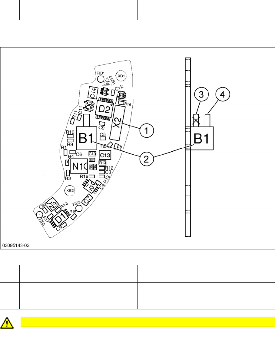
1.3 Vacuum Sensor Holding Circuit Board CP14
Vacuum Sensor Holding Circuit Board CP14
Vacuum sensor holding circuit board CP14
S1 DP Power ON 1-4 OFF
S1 Z down test 2-3 OFF
1 Plug X2 (to intermediate distributor) 2 Pressure sensor (holding circuit/aperture
ring)
3 Bottom hose connection on pressure sen-
sor
→ Do not use!
4 Top hose connection on pressure sensor
CAUTION
Only use the top hose connection
The bottom hose connection (3) directly above the board must remain free.
► Only use the top hose connection (4).
Description of the Circuit Boards CP14
Vacuum Sensor Holding Circuit Board CP14
6 Head PCB Overview Step by Step Analysis