CP45X-Y轴控制部分派断.pdf - 第3页
3. X-Y(Frame) Part Ver. Date CP45 CP45NEO 00 2004/11 O O 3-1 3-2. How to Distingui sh Parameter of Motor Driver Driver *T o o l s a) *P a r t a) 1) Parameter Distributed through SGSS Should be Used. The Way to Distinguis…
3. X-Y(Frame) Part
Ver. Date CP45
CP45NEO
00 2004/11 O O
3-1
3-1. Motor Driver Check and Replacement
*Tools
a)
*Part
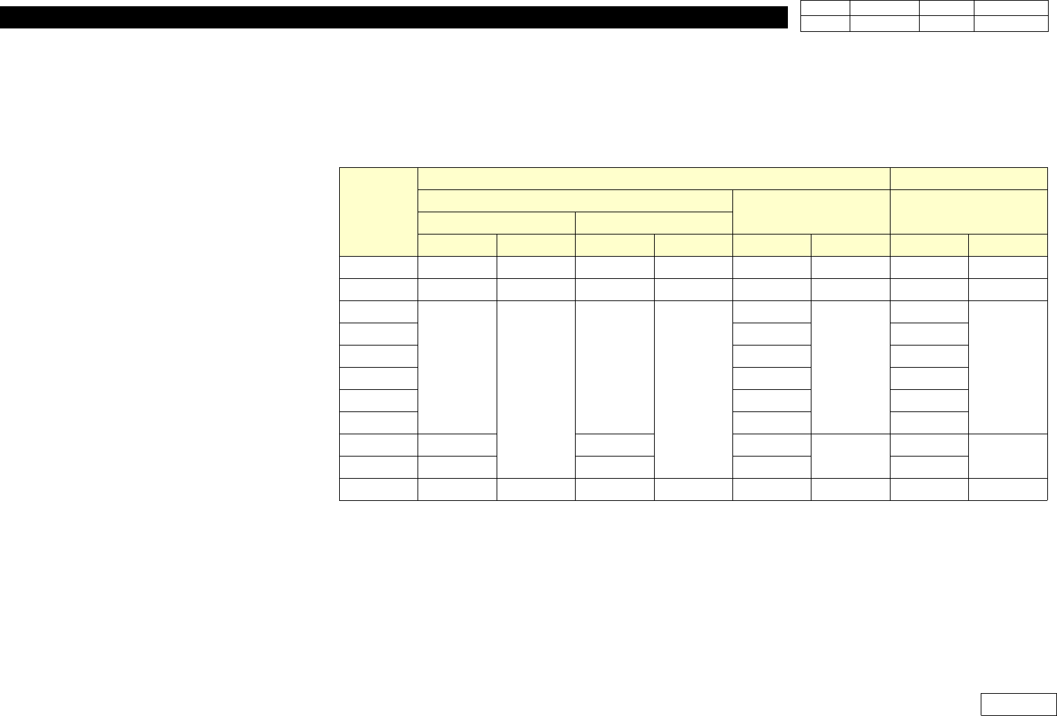
Refer the Table below for the Meterial Number of Motor Driver.
1) Refer 1-11 for Basic Replacement Procedure.
2) 'IBF1' Parameter in Driver Can be Adjusted in Case of Noise During X-axis Drive.
But, Procedure Should be Done by Direction of Samsung Techwin.
(Following is Limited to Tsubaki Ball Screw Applied Equipment)
- Check if IBF1 is Set to 270.(Default Value)
-MoveX-axistoCheckNoiseasChangingIBF1to200~1000.
Axis
CP45F(V) CP45F(V)NEO
PY Type(Sanyo)
Q Type (Sanyo) PType(Panasonic)
CE NON-CE
Motor Driver Motor Driver Motor Driver Motor Driver
X
J9061225B J3153012A J9061931B J3153026A J9075955A J3153044A J9080103A J3153034A
Y
J3108012A J1301684 J3108022A J3153025A J3108049A J3153045A J3108040A J3153052A
Z1
J9061962A
J3153014A
J9061968A
J3153024A
J9061962A
J3153043A
J9080110A
J3153032A
Z2
J9061963A J9080111C
Z3
J9061964A J9080112A
Z4
J9061965A J9080115A
Z5
J9061966A J9080116A
Z6
J9061967A J9080117B
Swing
J9061238D J9061934C J9075961A
J3153043A
J9080120B
J3153033A
C/V Width
J9061238D J9061935C J9075963B J9080123A
Theta
J3104008A J3152008A J3104012A J3152008A J3104012A J3152008A J3104012A J3152008A
3. X-Y(Frame) Part
Ver. Date CP45
CP45NEO
00 2004/11 O O
3-1
3-2. How to Distinguish Parameter of Motor Driver Driver
*Tools
a)
*Part
a)
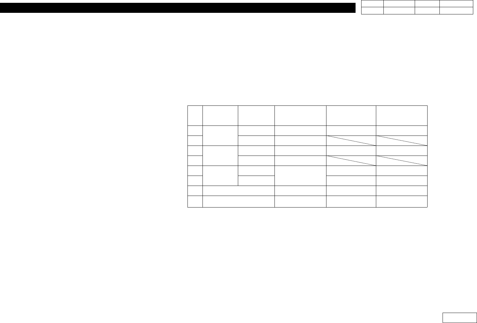
1) Parameter Distributed through SGSS Should be Used.
The Way to Distinguish Parameter File is as Follows.
No.
Axis Index
Ball Screw
Index
CP45F(V) CP45NEO
C45NEO-
Large PCB
1
X
KURODA 45_X_K.APO 45N_X.PRM 45N_X.PRM
2 TSUBAKI 45_X_T.APO
3
Y
KURODA 45_Y_K.APO 45N_Y.PRM 45N_Y_L.PRM
4 TSUBAKI 45_Y_T.APO
5
Z
H1,H3,H5
45_Z.APO
45N_Z135.PRM 45N_Z135.PRM
6 H2,H4,H6 45N_Z246.PRM 45N_Z246.PRM
7 Swing 45_S.APO 45N_S.PRM 45N_S.PRM
8 Width 45_W.APO 45n_W.PRM 45n_W.PRM
3. X-Y(Frame) Part
Ver. Date CP45
CP45NEO
00 2004/11 O O
3-1
3-3. X Ball Screw Change Process
*Tools
a) hex wrench set. Height gage and indicator.
*Part
a)Ball Screw (J6606014A),Bearing support (J7154090B), Bearing Bracket-X(J7154089B)
Support Unit(J6601086A),Coupling(J6012010A)
1) Remove Cover(Cover of right side of MC)
2) Disassemble Xaxis Motor and Coupling
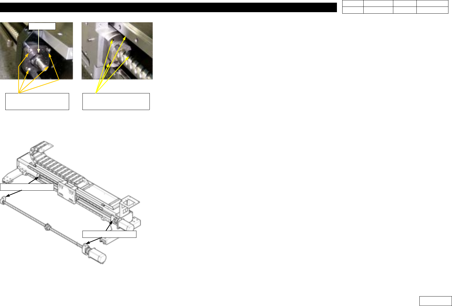
3) Remove Lock Nut, Support Unit(Fig 3-3-1)
4) Disassemble NUT of Ball Screw from Head Base
5) Remove Ball Screw(Remove direction to motor assemble side)
6) assemble new Ball Screw and Bearing and than locking by Ring
7) Assemble ball Screw by redirection.
8) Move Head Base to center and fasten nut of ball screw.
At this time, That space is 39.5(+,-)0.02mm between Top side of X axis L/M and Ball Screw Nut.
(Data form KURODA Ball Screw)
9) Assemble Support Unit and Lock Nut
10)Assenble Coupling and X axis motor.
*) attention : Please, do not remove Bearing Support and Bearing Bracket-X on X axis Frame.
* Adjustments after this work
- PCB origin offset,
- Feeder Base Origin Offset,
- ANC fiducial position and Hole position.
- Tray Feeder Origin
Fig.3-3-1 D isassemble the bolt for Support unit
& Nut(Ball screw).
Lock Nut
Bolt for Support Unit
(4EA)
Bolt for Ball screw nut
(4EA)
Fig.3-3-2 Note : Don't disassemble Bearing
Support and Bearing Bracket-X
Bearing Support
Bearing Bracket-X