CP45X-Y轴控制部分派断.pdf - 第7页
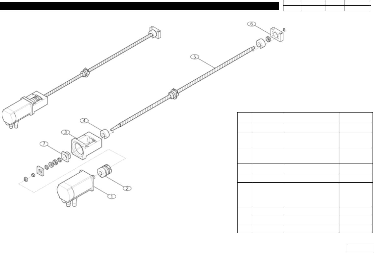
3. X-Y(Frame) Part Ver. Date CP45 CP45NEO 00 2004/11 O O 3-1 No. Code Discription Remark 1 J3108012A P20B10150HXS0E PY 1 J3108049A SERVO MOTOR [Q1AA10150HXSYKM] Q 2 J6612011A COUPLING [SFC050WD-12B22B] 3 J7054089B MOTOR …
3. X-Y(Frame) Part
Ver. Date CP45
CP45NEO
00 2004/11 O O
3-1
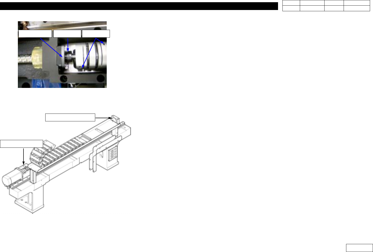
Fig.3-4-1
Fig.3-4-2 Note : Don't disassenble Motor
Bracket-Y, Bearing Support-Y
3-4. Procedure to Replace Y Ball Screw
*Tools
a) hex wrench set.
*Part
a)
1) Separate Cover.(Separate Up and Front OP Panel)
2) Separate Y-axis Motor and Coupling.
3) Separate Lock Nut, Support Unit. (Ref. Fig 3-4-1)
4) Separate Nut of Ball Screw.
5) Separate Ball Screw.(To the Direction Motor is Assembled)
6) Assemble Bearing to New Ball Screw and Lock it with Ring.
7) Assemble Ball Screw the Opposite way it is De-Assembled.
8) Lock Nut of LM Plate and Ball Screw.
9) Assemble Support Unit and Lock Nut.
10) Assemble Coupling and X-axis motor.
*) Note : Do not Separate Bearing Support-Y and Bearing Bracket-Y Assembled at Y-axis Frame
to Maintain Assembly Precision between Parts when Assembled at Factory.
(Ref. Fig 3-4-2)
* Adjustments after this work
- PCB origin offset
- Feeder Base Origin Offset
- ANC fiducial position and Hole position.
- Tray Feeder Origin
Lock NutSupport Unit Coupling
Motor Bracket-Y
Bearing Support-Y
3. X-Y(Frame) Part
Ver. Date CP45
CP45NEO
00 2004/11 O O
3-1
No. Code Discription Remark
1 J3108012A P20B10150HXS0E PY
1 J3108049A
SERVO MOTOR
[Q1AA10150HXSYKM]
Q
2 J6612011A
COUPLING
[SFC050WD-12B22B]
3 J7054089B MOTOR BRACKET-Y
4 J7254007C CUSHION-Y(Kuroda)
5 J6606013A
BALL SCREW
[GH2040QS-HEZR-116
0X1058-C5F]
Kuroda
6
J7054084A BEARING SUPPORT-Y
J1300510 BEARING [6002ZZ]
7 J7054084A BEARING SUPPORT-Y
3. X-Y(Frame) Part
Ver. Date CP45
CP45NEO
00 2004/11 O O
3-1
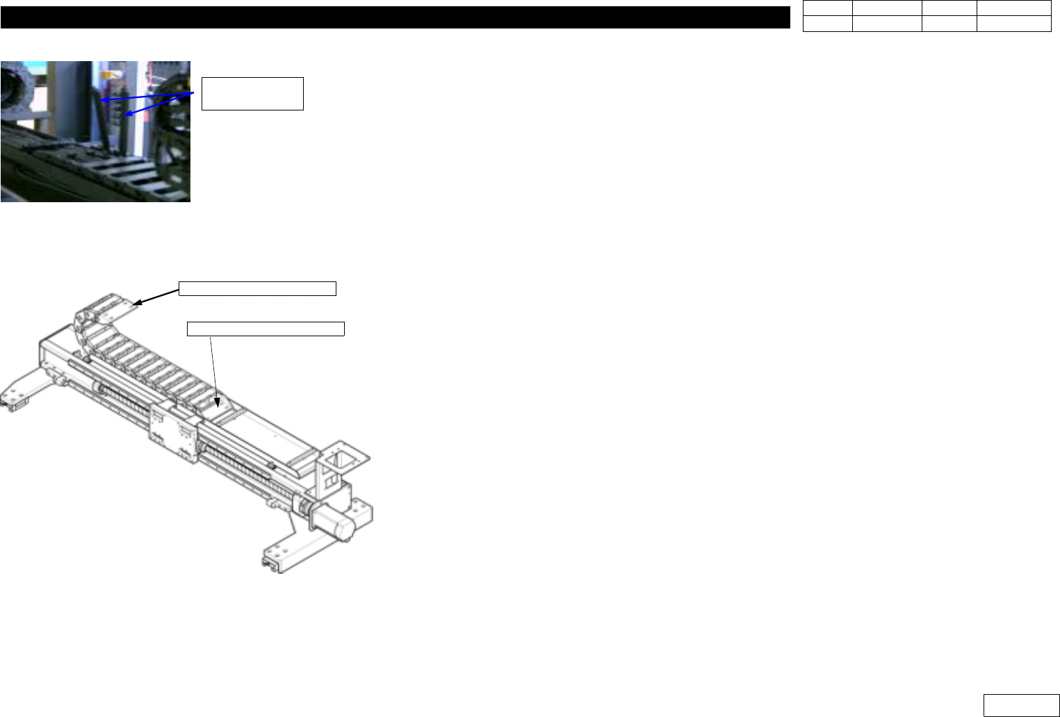
3-5. X-axis Cableveyor Replacement
*Tools
a) +Driver, Hex Wrench
*Part
a) Cableveyor
1) Erect Cover of Each Link of Existing Cableveyor. (Ref. Fig 3-5-1)
2) Separate Locked Bolt of Fixed End Bracket and Moving End Bracket. (Ref. Fig 3-5-2)
3) Carefully Separate Cableveyor.
4) Erect Cover of New Cableveyor.
5) Assemble Cableveyor between Cable.
6) Arrange Cable to Designated Location Using Divider. (Ref. X-axis Cableveyor Section
Drawing)
7) Assemble Locked Bolt of Fixed End Bracket and Moving End Bracket.
8) Assemble Cover of Cableveyor.
* Note 1) Check if Cable is Damaged to Replace with New One or Insulated Tape.
2) Cable Arrangement Should be Done to Designated Location. Cable Wear Can be
Increased by Difference between Inner and Outer Distance if the Location is Changed.
* Adjustments after this work
None
Bolts of Moving end bracket
Bolts of Fixed end bracket
Fig.3-5-2 Fixed end bracket &
Moving end bracket
Erect the all cover
of each link
Fig.3-5-1 Erect all cover of each link