00198576-01_JG_Nozzles_E-by-SIPLACE_EN.pdf - 第9页
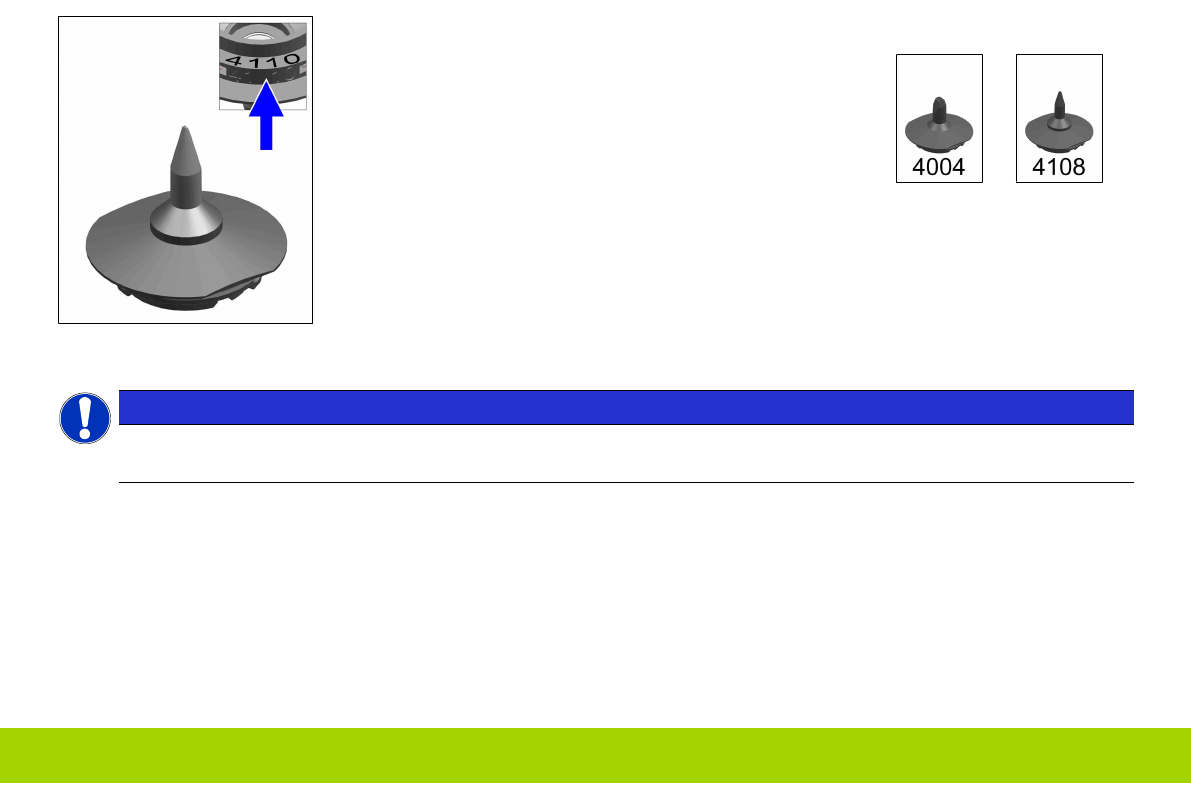
1 - 5 www.e-by-siplace.com Nozzle series 4xxx: These nozzles are used on the SIPLACE CP14 . All nozzles in this series have a 4-digit number code on the outer and top side. Examples: NOTICE ESD security The materials (pl…
1 - 4
www.e-by-siplace.com
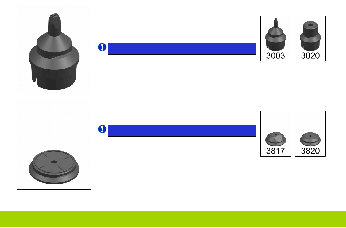
Nozzle series 7xx / 9xx / 30xx:
These nozzles are used on the SIPLACE CP6 and the
SIPLACE CP12.
All nozzles in this series have a 4-digit number code on the
top outer side.
NOTICE!
7xx, 9xx and 30xx nozzles are of identical design
and can be used accordingly.
A 905 nozzle is mechanically identical to a 3005 nozzle.
.
Examples:
Nozzle series 8xx / 38xx:
These nozzles are used on the SIPLACE CP6.
All nozzles in this series have a number code on the inside.
NOTICE!
8xx and 38xx nozzles are of identical design and can
be used accordingly.
A 817 nozzle is mechanically identical to a 3817 nozzle.
.
Examples:
1 - 5
www.e-by-siplace.com
Nozzle series 4xxx:
These nozzles are used on the SIPLACE CP14.
All nozzles in this series have a 4-digit number code on the
outer and top side.
Examples:
NOTICE
ESD security
The materials (plastic, ceramic and rubber) of the listed nozzles are ESD proof.
1 - 6
www.e-by-siplace.com
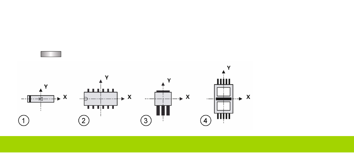
0° Description of Components
In order to work with component shapes which have uniform definitions, standard components are described using four
specific rules. This is known as the "0° description" position, which allows you to precisely define the pickup angle during
placement.
To describe the component shape of a component, the dimensions should always be taken from the corresponding data
sheet. Make sure that the component is always described as viewed from above.
The display area of the GF Editor always shows the 0° description of the component. This zero degree origin of the co-
ordinate system is always shown in the center of the GF Editor display area. The X axis points to the right and the Y axis
points upwards. The center of the component generally corresponds to the origin of the coordinate system. Rule 1 defines
the alignment of the component sides in the X or Y directions.
Rule 1: A nozzle with rectangular suction surface is aligned with its longer side along the X axis. The component X
axis is parallel to the nozzle X axis, when the nozzle picks up the component properly.
When picking up a component, the component X axis always points in the same direction as the long side of the nozzle
(exception: special nozzles with 90° rotation).
The X axis of the component does not necessarily have to be the long side of the component.
For example, if there are holes through the component, the the nozzle will have to attach at a 90° angle (see fig. (4),
nozzle =
).