Integration Stanzförderer.pdf - 第10页
Nachrüstanleitung SOKO Integration Stanzförde rer HF-Serie Ausgabe 11/2004 10 : Brin gen Si e ein Hin weiss child an , das auf die mec hanis che S perre des BE- W a gens hinwei st. 1 W ar nschi lder bz gl. Qu etschgefahr…
Nachrüstanleitung SOKO Integration Stanzförderer HF-Serie
Ausgabe 11/2004
9
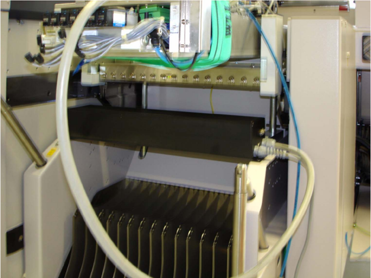
: Montieren Sie die Steuerung des Förderers am BE-Wagen.
1
1
1
1
1
1
1
1
1
1
1
1
1
1
1
1
Nachrüstanleitung SOKO Integration Stanzförderer HF-Serie
Ausgabe 11/2004
10
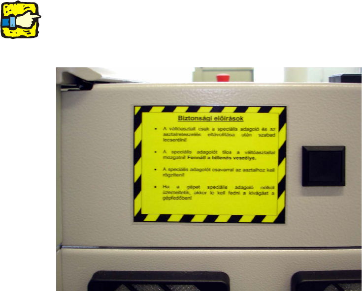
: Bringen Sie ein Hinweisschild an, das auf die mechanische Sperre des BE-Wagens hinweist.
1
Warnschilder bzgl. Quetschgefahr im Stanzbereich des Förderers liegen im Verantwortungsbe-
reich des Kunden. 1
1
1
1
1
1
1
1
1
1
1
1
1
1
Retrofit Instructions - Special Design for Integrating the Punching Die Feeder for the HF series
11/2004 Edition
11
2 Retrofit Instructions - Special Design
for Integrating the Punching Die
Feeder for the HF series
2.1 Restrictions
– The feeder must be bolted to the component table, otherwise it would not be possible to fix the
pick-up position. There is also a risk of accident if the feeder is not fixed.
– The feeder and the component table lock must both be removed before the component table
is replaced.
– If the modified feeder area is operated without a special feeder, then the customer is respon-
sible for providing a suitable hand guard.
– The risk of crashing in the event of a feeder fault cannot be excluded since communication be-
tween the feeder and machine is lost.
– No "flat" component tapes can be used in the feeder area of the special feeder since the re-
ducer has to be removed from the tape removal channel.
– The special feeder can only be set up at location 2, track 49-90.
– The feeder is not supported by SIPLACE Pro and can only be described as a linear feeder with
a suitable offset.
– Siemens L&A does not guarantee that the feeder will work correctly.
2
2
2
2
2
2
2
2
2
2