00196496-07_SM_SX12DX12_Kunde_de.pdf - 第300页
Platinenbeschreibung Elektrik und Steuerung 5.1.2 GCU/MGCU 300 Serviceanleitung SIPLACE SX1/SX2/DX1/DX2 FS02 5.1.2.2 5 . 1 . 2 . 2 D ia g n o s e - I n t e r f a c e [ 0 3 0 7 5 8 1 3 - x x ] Diagnose-Interface [03075813…
Platinenbeschreibung
5.1.2 GCU/MGCU Elektrik und Steuerung
Serviceanleitung SIPLACE SX1/SX2/DX1/DX2 FS02 299
5.1.2
5.1.2 GCU/MGCU
GCU/MGCU
5.1.2.1
5.1.2.1 Regeleinheit GCU-CM [03060951-xx]
Regeleinheit GCU-CM [03060951-xx]
03060951-03
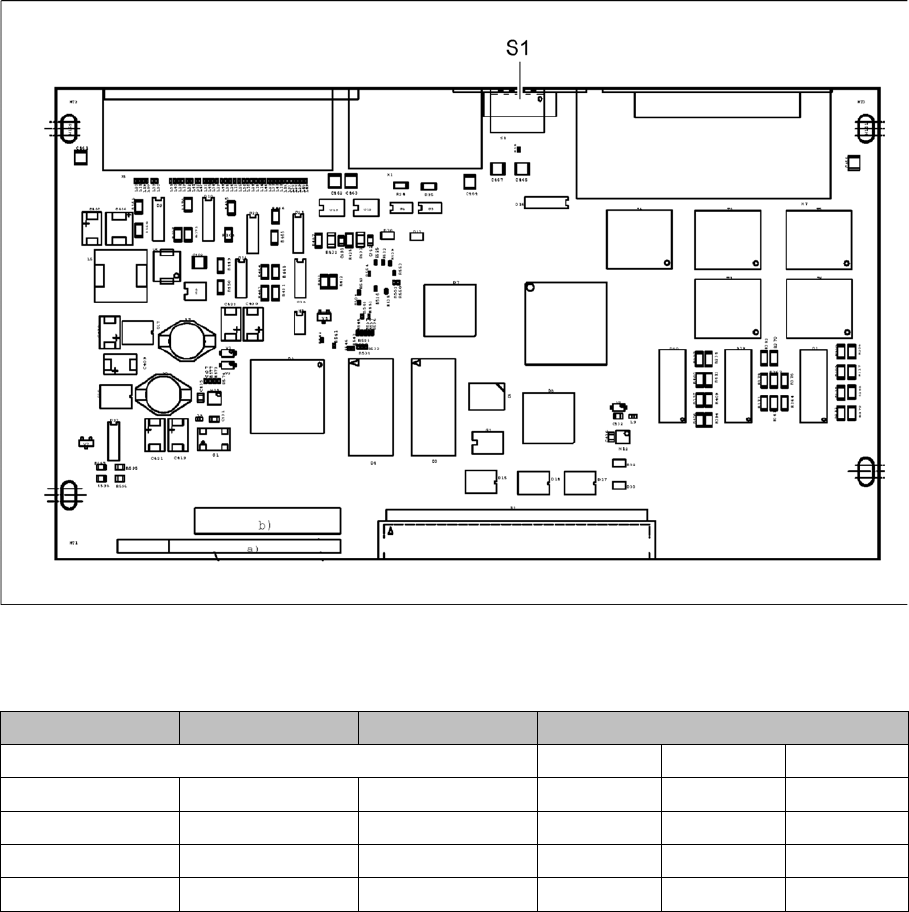
Diese Platine ist in der GCU verbaut.
DIP-Schalter S1 [03060951-03]
Schalter Status Signalname Beschreibung
GCU1 GCU2 GCU3
S1.1 ON/OFF Portal_ID_0 ON OFF OFF
S1.2 ON/OFF Portal_ID_1 OFF OFF ON
S1.3 ON/OFF Portal_ID_2 ON OFF ON
S1.4 ON/OFF Portal_ID_3 OFF OFF OFF
Platinenbeschreibung
Elektrik und Steuerung 5.1.2 GCU/MGCU
300 Serviceanleitung SIPLACE SX1/SX2/DX1/DX2 FS02
5.1.2.2
5.1.2.2 Diagnose-Interface [03075813-xx]
Diagnose-Interface [03075813-xx]
03075813-01
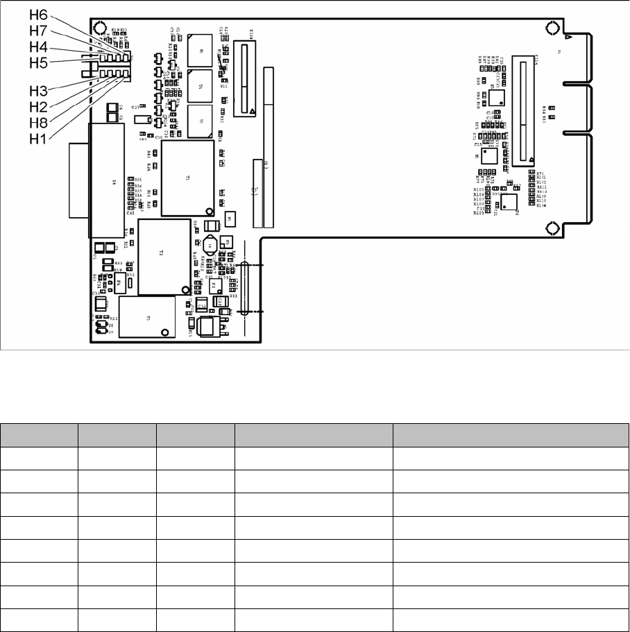
Diese Platine ist in der GCU verbaut.
LED [03075813-01]
LED Farbe Status Signalname Beschreibung
H1 RD ON LED_ERROR Fehleranzeige
H2 GN ON A1_LED_PM_ON_N Powermodul aktiviert, Achse 1
H3 GN ON A2_LED_PM_ON_N Powermodul aktiviert, Achse 2
H4 GN ON A1_LED_END Endemeldung, Achse 1
H5 GN ON A2_LED_END Endemeldung, Achse 2
H6 GN ON LED_READY Ready
H7 GN ON P24V +24VDC
H8 GN ON P5V +5VDC
Platinenbeschreibung
5.1.3 I/O Control Unit [03116049-xx] Elektrik und Steuerung
Serviceanleitung SIPLACE SX1/SX2/DX1/DX2 FS02 301
5.1.3
5.1.3 I/O Control Unit [03116049-xx]
I/O Control Unit [03116049-xx]
Übersicht
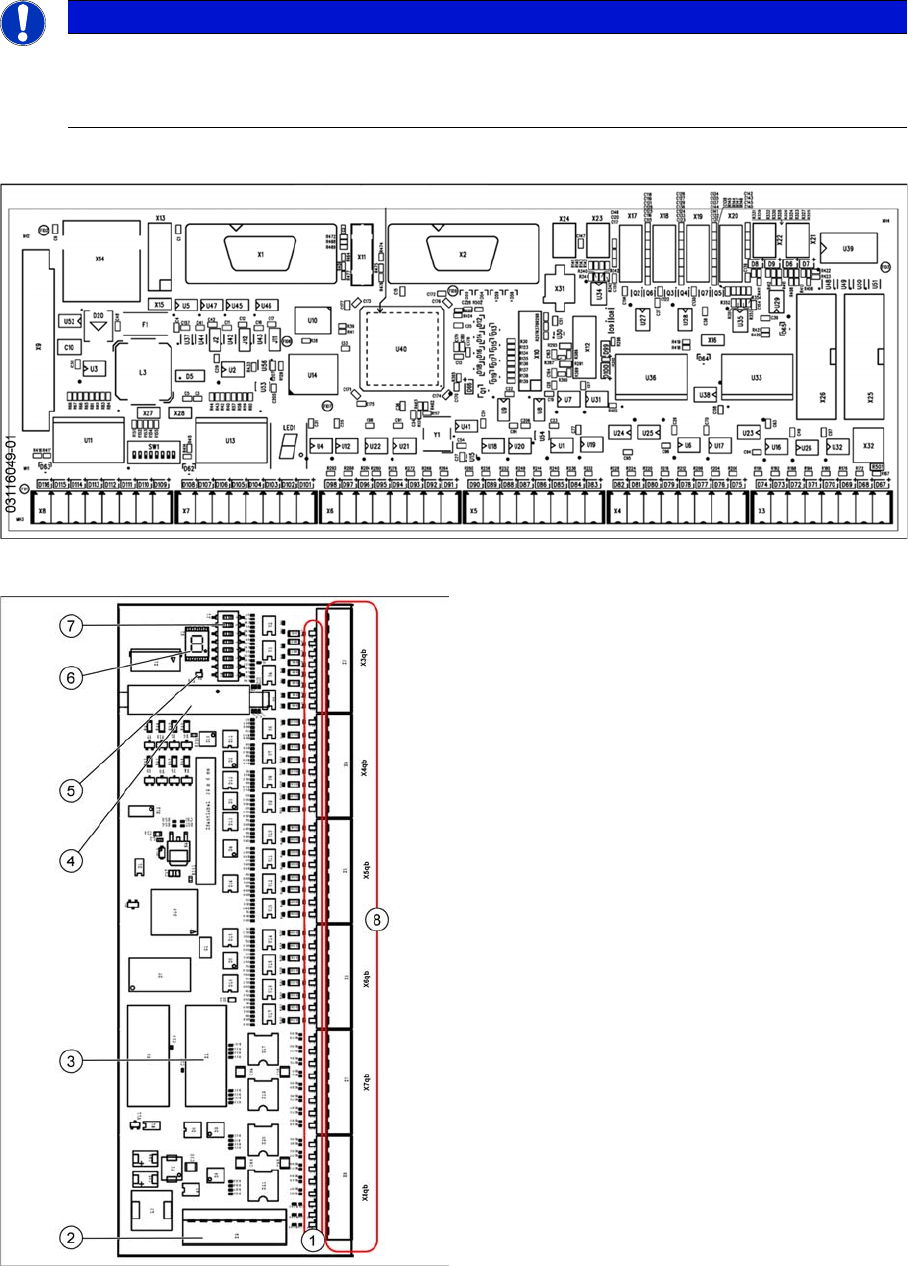
03116049-01
HINWEIS
Abwärtskompatibel
Die I/O Control Unit II [03116049-xx] ist abwärtskompatibel zur I/O-Control-Unit [03052315-xx].
Alle Anschlüsse und Bezeichnungen sind identisch.
Übersicht I/O-Control-Unit [03052315-xx]
1. Status-LEDs
2. X9qb: Stromversorgung
3. X1qb: CAN-Bus 1
4. X10qb: Anschluss weiterer I/O
-
Module möglich
5. Rote LED
Diese signalisiert einen RESET.
6. H1: 7-Segment Anzeige
(Blinkend = O.K.)
7. DIP-Schalter S1
8. Ausgänge X3qb bis X8qb