Foreign Machine Interface.pdf - 第22页
FOREIGN MACHINE INTERFACE MULTI-INTERFACE UNIT 28.22 Technical Reference Manu al Chapter Issue 3 Jan 08 Power Supplies The MIU is mounted behind the front p anel of the machine and re ceives its power supplies via the ma…
FOREIGN MACHINE INTERFACE
MULTI-INTERFACE UNIT
Chapter Issue 3 Jan 08 Technical Reference Manual 28.21
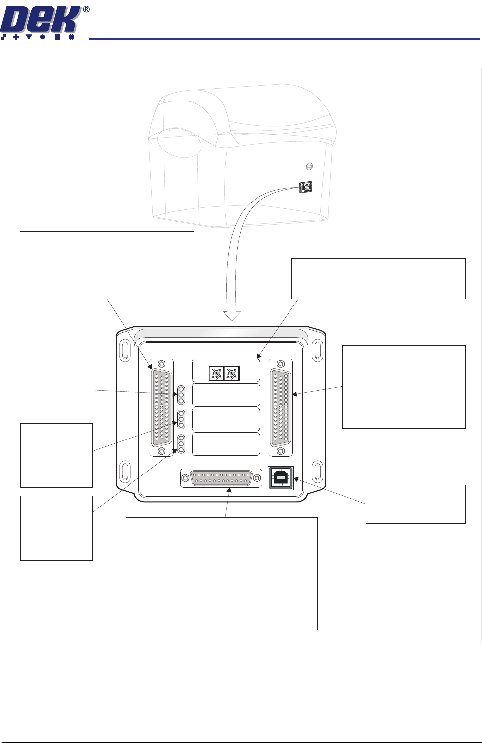
Figure 28-2 Multi-Interface Unit Connectors and Indicators
M1SK1
UPLINE
M1SK2
DOWNLINE
M1PL3
DEK M/C
M1SK4
DEK USB
+12V
+24V
+24V SW
SEND UPLINE
SEND DOWNLINE
CONTROL IN
UPLINE READY
DOWNLINE READY
CONTROL OUT
POWER
I/P'S
O/P'S
PROTOCOL SELECTION
UP
LINE
DOWN
LINE
MIU 191114
Protocol Selection
Upline interface select switch.
Downline interface select switch.
M1SK1
Signal lines to and from the DEK machine
from the upline machine.
4 Inputs: Opto-isolated.
4 Outputs: Lowside driver.
4 Outputs: Solid State Relay switched.
LED Bank LD1
Shows the
integrity of
the derived
supplies
LED Bank LD2
Indicates the
(Inputs)
sequence of
events during
board transfers
LED Bank LD3
Indicates the
s
(Outputs)
sequence of
events during
board transfer
M1SK2
Sign
4 Inputs: Opto-isolated.
4 Outputs: Lowside driver.
4 Outputs: Solid State
Relay switched.
al lines to and from
the DEK machine from
the downline machine.
DEK USB connection
not used.
M1SK4
M
1
S
K
1
U
P
L
I
N
E
M
1
S
K
2
D
O
W
N
L
I
N
E
M
1
P
L
3
D
E
K
M
/
C
M
1
S
K
4
D
E
K
U
S
B
+
1
2
V
+
2
4
V
+
2
4
V
S
W
S
E
N
D
U
P
L
I
N
E
S
E
N
D
D
O
W
N
L
I
N
E
C
O
N
T
R
O
L
I
N
U
P
L
I
N
E
R
E
A
D
Y
D
O
W
N
L
I
N
E
R
E
A
D
Y
C
O
N
T
R
O
L
O
U
T
P
O
W
E
R
I
/
P
'
S
O
/
P
'
S
P
RO
T
OC
OL
S
ELE
CTI
ON
U
P
L
I
N
E
D
O
W
N
L
I
N
E
M
I
U
1
91
114
4
8
0
4
8
0
M PL31
Power supplies.
Comms connections to the DEK machine
Inputs to the DEK machine from interface -
1. Downline Ready
2. Upline Ready
3. Control In
Outputs from the DEK machine to interface -
1. Send Downline
2. Send Upline
3. Control Out
4
80
4
80
FOREIGN MACHINE INTERFACE
MULTI-INTERFACE UNIT
28.22 Technical Reference Manual Chapter Issue 3 Jan 08
Power Supplies The MIU is mounted behind the front panel of the machine and receives its
power supplies via the machine controller enclosure. Derived supplies are
made available for the upline and downline interfacing (0V is common).
The power supplies are fused on board with self resetting poly fuses.
NOTE
+24V (Switched) is removed when the machine E Stop is pressed.
Multi-Interface Unit Block Diagram
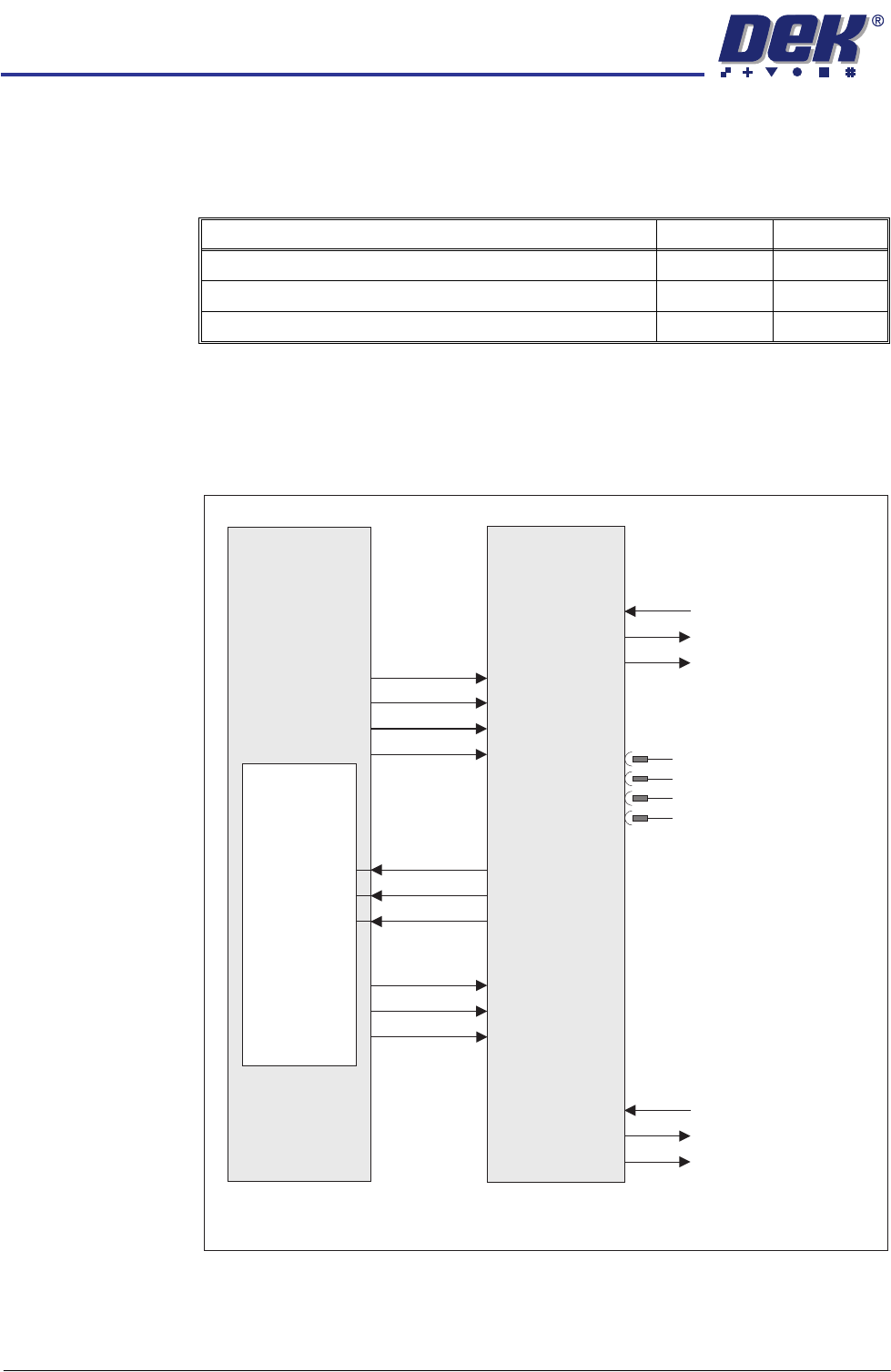
Figure 28-3 Machine Controller - MIU Block Diagram
Power Supply Fuse Rating
+12V FS2 1A
+24V Switched FS1 1A
+24V - Unswitched FS3 1A
DEK Interface
(FMI Loom)
Multi-Interface
Unit
M36 Machine
Controller
NextMove
Interface Card
24V US
DIG OUT 5
DIG OUT 6
DIG OUT 7
0V
12V
4 Opto Isolated I/P’s
M1SK1
M1SK4
M1SK2
M1PL3
24V SW
4 Solid State Relay O/P’s
4 O/P’s (Lowside Drivers)
DIG IN 16
DIG IN 17
DIG IN 18
Upline Ready
Downline Ready
Control Out
M36SK04
Send Upline
Send Downline
Control In
4 Opto Isolated I/P’s
4 Solid State Relay O/P’s
4 O/P’s (Lowside Drivers)
Upline Machine
Downline Machine
USB
(not used)
FOREIGN MACHINE INTERFACE
MULTI-INTERFACE UNIT
Chapter Issue 3 Jan 08 Technical Reference Manual 28.23
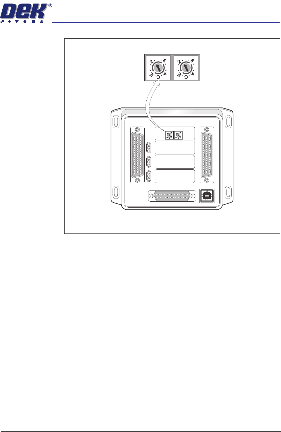
Protocol Selection
Figure 28-4 Interface Selector Switches
M1SK1
UPLINE
M1SK2
DOWNLINE
M1PL3
DEK M/C
M1SK4
DEK USB
+12V
+24V
+24V SW
SEND UPLINE
SEND DOWNLINE
CONTROL IN
UPLINE READY
DOWNLINE READY
CONTROL OUT
POWER
I/P'S
O/P'S
PROTOCOL SELECTION
UP
LINE
DOWN
LINE
MIU 191114
4
80
4
80
4
80
4
80
Upline Interface
Selector Switch (SW2)
Downline Interface
Selector Switch (SW3)