00193365-0202.pdf - 第21页
Retrofit instructions Splice sensors 8 - 72 mm 07/2003 Edition 21 : Use th e M 3x25 mm s crew s to fi x the sensor to the feeder at t he point p re viously u sed to fix the tape guide plate. Y ou w ill need one or both s…
Retrofit instructions Splice sensors 8 - 72 mm
07/2003 Edition
20
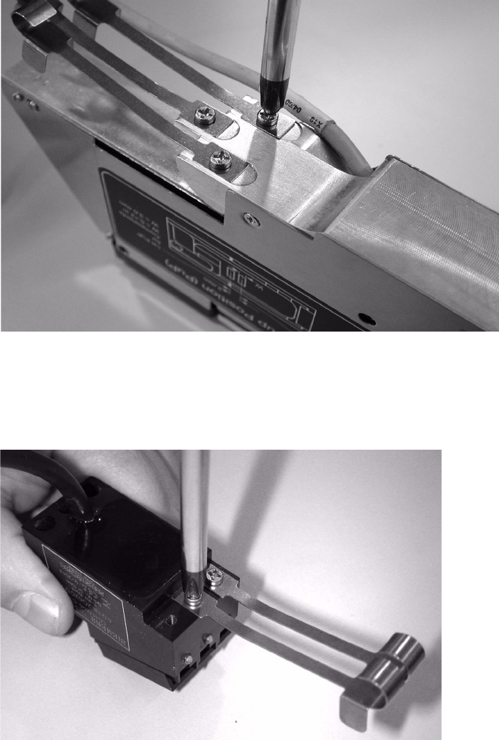
: Remove the tape guide plate from the feeder.
3
Fig. 3 - 3 Unscrewing the tape guide plate
3
: Fix the tape guide plate to the sensor block using the same screw.
3
Fig. 3 - 4 Fixing the tape guide plate
3
3
3
Retrofit instructions Splice sensors 8 - 72 mm
07/2003 Edition
21
: Use the M3x25 mm screws to fix the sensor to the feeder at the point previously used to fix the
tape guide plate. You will need one or both screws, depending on the feeder.
3
Fig. 3 - 5 Fixing the sensor to the feeder
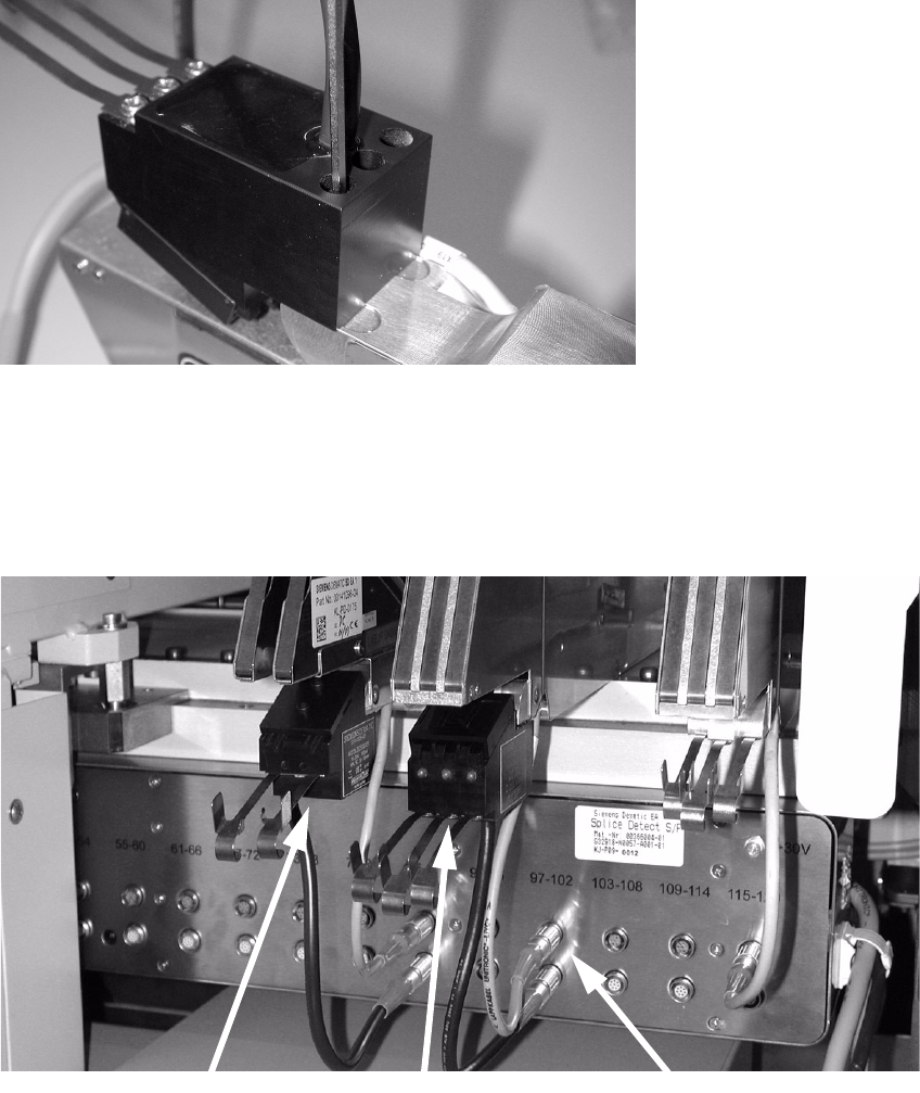
: Place the feeder back on the component feeder table and connect it up. Then place the splice
sensor in the appropriate socket on the lower socket block.
: Guide the tape over the tape guide plate into the sensor, and then through the feeder as usual.
3
Fig. 3 - 6 Feeder with splice sensors, connected
3
3
3x8 mm feeder
2x8 mm feeder
Terminals
Retrofit instructions Splice sensors 8 - 72 mm
07/2003 Edition
22
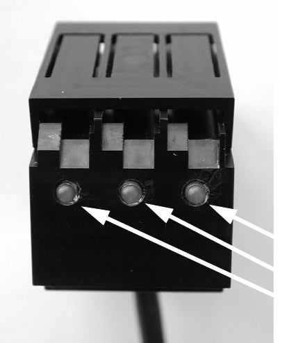
The LEDs on the splice sensors have the following meaning: 3
– LED on: Ready
– LED off: Splice detected
3
Fig. 3 - 7 LEDs on the splice sensor
3
3
LEDs