00193365-0202.pdf - 第26页
Retrofit instructions Splice s ensors 8 - 72 m m 07/2003 Edition 26 Rea dy S plic e Dete ct Se nsor 4 : For the 12/1 6 wide kit an d the 24/32 kit, determine which tape/feeder wi dth you need. Both kits ar e shipped pr e…
Retrofit instructions Splice sensors 8 - 72 mm
07/2003 Edition
25
4.3 Installation Instructions
Prepare feeder 4
: After removal of feeder, remove (2) phillips head screws holding the communications cable
bracket, and save bracket with screws.
4
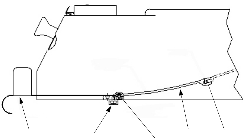
Fig. 4 - 3 Removal of existing spring guide and holding bracket
4
: Remove (2) side phillips head screws, one each side of Feeder, holding the tape guide spring
holding bracket inside of the feeder.
Save these screws.
: Pull the bracket straight out towards the rear of the feeder. Pivot up and down slightly to loosen
bracket as you pull.
The bracket may be tight and difficult to remove, but it does come out.
: Pull bracket and spring completely out of feeder.
4
: Remove the (2) M3 x 4 flat head screws holding the tape guide spring and discard the spring,
but save these (2) screws. See Fig. 4 - 1.
4
4
Pins
Holding
bracket
Phillips head
screws
Tape guide
spring
Comm.cable holding
bracket w/screws
Retrofit instructions Splice sensors 8 - 72 mm
07/2003 Edition
26
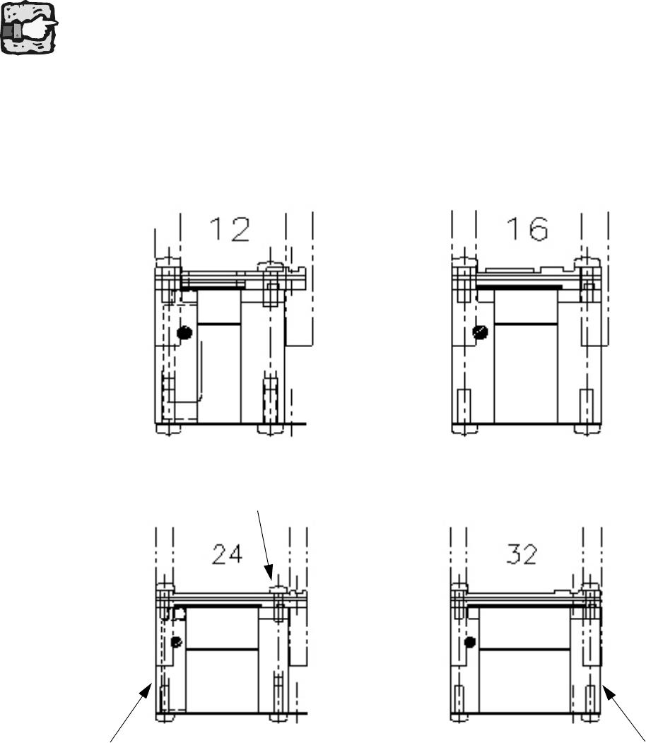
Ready Splice Detect Sensor 4
: For the 12/16 wide kit and the 24/32 kit, determine which tape/feeder width you need.
Both kits are shipped pre-assembled in the smaller tape/feeder position. The upper lid can be
flipped over (180 deg.) to accommodate the larger width. 4
4
No spring guide at the 24/32 splice sensor! 4
4
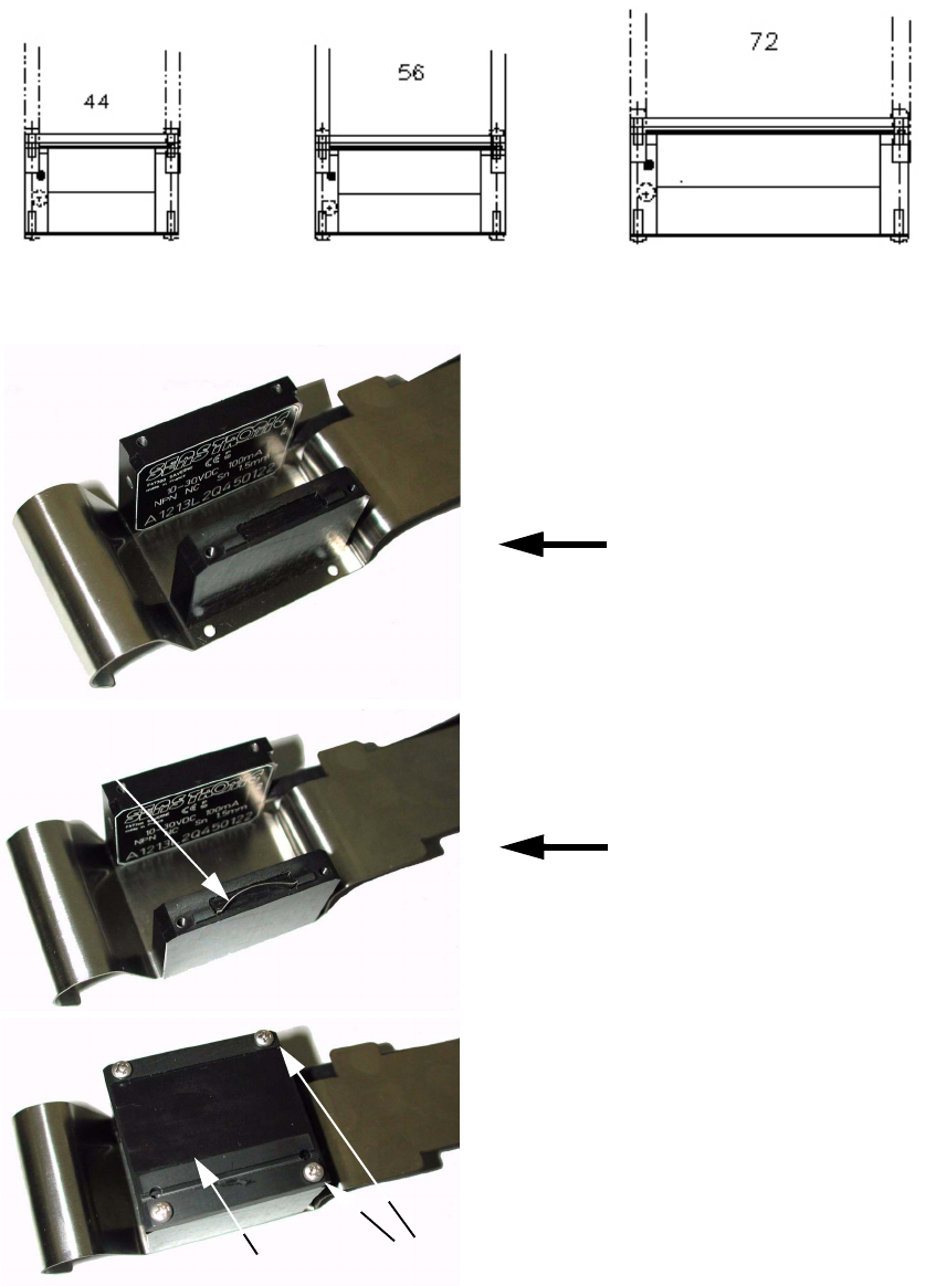
: Using the supplied M 2.5 x 8 pan head screws, mount the right side guide block in the appro-
priate holes in the kit spring bottom with the upper tape notch facing inboard the same way it
was received.
: Then mount the lid piece in the corresponding slots and screw in place with the supplied pan-
head screws. See Fig. 4 - 2.
4
Movable guide block
M2.5x8 Pan HD screw
Fixed sensor block
Retrofit instructions Splice sensors 8 - 72 mm
07/2003 Edition
27
For the 44, 56, and 72 wide kits, they are shipped pre-assembled ready to install. 4
4
Fig. 4 - 4 End views of 44, 56, & 72 wide kits
4
Fig. 4 - 5 Splice Sensors
Blade spring
Setting the 32 mm position
Setting the 24 mm position
Cover
4 screws