00198442-01_UM_TX-V2_EN.pdf - 第184页
4 Setting up and commissioning User manual SIPLACE TX V2 4.5 Setting up the placement machine From software version 711.1 04/2018 184 4.5.5.3 Pallet truck specification for lif ting at the locations The pallet truck must…
User manual SIPLACE TX V2 4 Setting up and commissioning
From software version 711.1 04/2018 4.5 Setting up the placement machine
183
4.5.5.2 Fork-lift attachment points on the placement machine
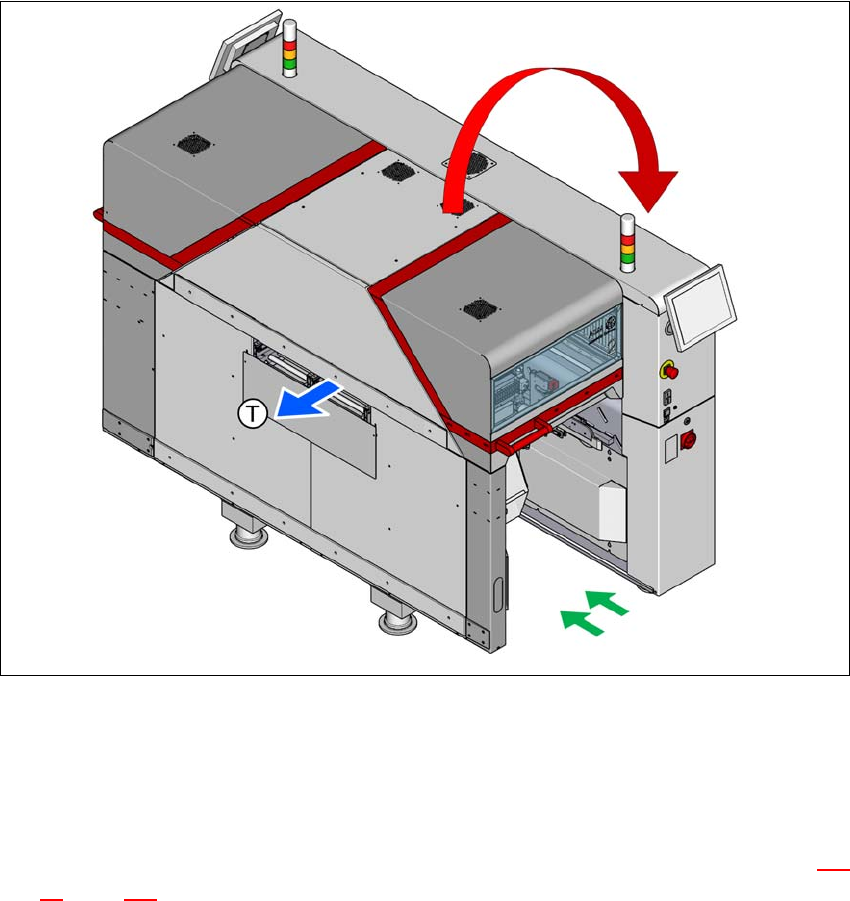
A pallet truck may be used to lift the placement machine at the locations, to place it in the line or
lift it out of the line.
4
Fig. 4.5 - 4 Placing the machine into a line or lifting it out of a line
(T) Direction of travel for PCB conveyor
(1) Pallet truck forks
(2) Risk of tilting due to eccentric center of gravity.
Position the forks of the pallet truck in the location area. The steel spacers (item 2 in fig. 4.5
- 3, page 181) limit the fork position so that the center of placement machine gravity is com-
pensated.
Open the forks until the forks are up against the metal sheets for limiting the fork positions
and the contact surfaces of the placement machine can lie evenly on the forks.
Push the forks into the location area, so that the machine can lie safely along the whole length
of the forks.
Positioning the placement machine in the line.
(2)
(1)

4 Setting up and commissioning User manual SIPLACE TX V2
4.5 Setting up the placement machine From software version 711.1 04/2018
184
4.5.5.3 Pallet truck specification for lifting at the locations
The pallet truck must compensate the uneven weighting on its forks and guarantee a horizontal
position when loaded.
If you lift the placement machine at the locations, you will need to use a pallet truck with the fol-
lowing specifications:
4
4
Fork length Min. 1800 mm
Lifting power Min. 3000 kg

User manual SIPLACE TX V2 4 Setting up and commissioning
From software version 711.1 04/2018 4.5 Setting up the placement machine
185
4.5.6 Setting the conveyor height and aligning the machine
4.5.6.1 PCB conveyor height on the placement machine
The machine can be set to the following PCB conveyor heights:
900 mm ± 15 mm 4
930 mm ± 15 mm (standard height) 4
950 mm ± 15 mm (SMEMA height) 4
4
4.5.6.2 Tools and equipment
You will need the following tools and equipment to adjust and set the height of your placement
machine:
– Torque wrench 100 Nm to 400 Nm, item no. 03122973-01
– Tool holder for reversible ratchet 800mm, item no. 03122976-01
– Attachable ratchet 34 inch 14x18, item no. 03122977-01
– Extension 1/2 inch, item no. 03080499-01
– 03122975-01 Inbus bit SW19x85mm 34 inch, item no. 03122975-01
– 03122979-01 UVEX bump cap SHORT. Item no. 03122979-01
– Hexagonal screwdriver bit, size 14
– Fork wrench 18 mm
– Shaft spirit level (accuracy 0.02 mm/m), item no. 00353825-01
– Pallet truck (specifications see 4.5.5.3 on page 184).
– Air cushion transport system: SIPLACE HSxx, Item No. 00119002-S01 (optional)
PLEASE NOTE
The PCB conveyor height is the distance between the top edge of the PCB conveyor belt
and the bottom edge of the placement machine feet.