00198442-01_UM_TX-V2_EN.pdf - 第186页
4 Setting up and commissioning User manual SIPLACE TX V2 4.5 Setting up the placement machine From software version 711.1 04/2018 186 4.5.7 Setting the conveyor height The machine stands on fo ur machine feet. 4 Fig. 4.5…

User manual SIPLACE TX V2 4 Setting up and commissioning
From software version 711.1 04/2018 4.5 Setting up the placement machine
185
4.5.6 Setting the conveyor height and aligning the machine
4.5.6.1 PCB conveyor height on the placement machine
The machine can be set to the following PCB conveyor heights:
900 mm ± 15 mm 4
930 mm ± 15 mm (standard height) 4
950 mm ± 15 mm (SMEMA height) 4
4
4.5.6.2 Tools and equipment
You will need the following tools and equipment to adjust and set the height of your placement
machine:
– Torque wrench 100 Nm to 400 Nm, item no. 03122973-01
– Tool holder for reversible ratchet 800mm, item no. 03122976-01
– Attachable ratchet 34 inch 14x18, item no. 03122977-01
– Extension 1/2 inch, item no. 03080499-01
– 03122975-01 Inbus bit SW19x85mm 34 inch, item no. 03122975-01
– 03122979-01 UVEX bump cap SHORT. Item no. 03122979-01
– Hexagonal screwdriver bit, size 14
– Fork wrench 18 mm
– Shaft spirit level (accuracy 0.02 mm/m), item no. 00353825-01
– Pallet truck (specifications see 4.5.5.3 on page 184).
– Air cushion transport system: SIPLACE HSxx, Item No. 00119002-S01 (optional)
PLEASE NOTE
The PCB conveyor height is the distance between the top edge of the PCB conveyor belt
and the bottom edge of the placement machine feet.
4 Setting up and commissioning User manual SIPLACE TX V2
4.5 Setting up the placement machine From software version 711.1 04/2018
186
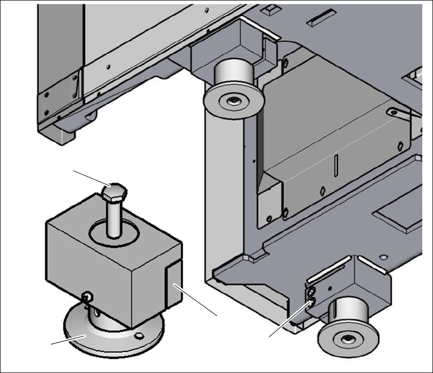
4.5.7 Setting the conveyor height
The machine stands on four machine feet.
4
Fig. 4.5 - 5 Setting the PCB conveyor height
(1) Setting screw for height adjustment
(2) Machine foot
(3) Clamping
(4) Two clamping screws
Loosen the two clamping screws (4), using the attachable ratchet and the hexagonal screw-
driver bit, size 14.
4
(1)
(4)
(3)
(2)
User manual SIPLACE TX V2 4 Setting up and commissioning
From software version 711.1 04/2018 4.5 Setting up the placement machine
187
4
4
Loosen the three other placement machine feet (2) in the same way.
Use the 18 mm open-end wrench, to change the height of the placement machine feet (2)
with the setting screw (1), in order to reach the relevant conveyor height.
4
Adjust the placement machine (see section 4.5.7.1, page 188).
WARNING
Only loosen the clamping screws with the attachable ratchet
The clamping screws may not be loosened using the torque wrench. There is a risk of
causing injuries.
To loosen the clamping screws, only use the attachable ratchet with the appropriate
extension.
WARNING
Perform work only with the bump cap and protective gloves.
There is a risk of causing injuries to the head and hands.
Only perform work with the bump cap and protective gloves.
PLEASE NOTE
Position of setting screws for height adjustment
On the output side, the setting screws are next to the component inserts.
On the input side, the setting screws are concealed, under the power supply unit. If the
optional vacuum pump is fitted, the other setting screw is hidden by the vacuum pump
and is located below this.