OM-1273-004_w.pdf - 第186页
5-23 AJK-ML T-ID 0706-002 4.1 Electrical and Electronic Symbols (a) (b) S S S S S S S S Name Symbols Graphical Symbols Remarks Cycle Counter Emergency Stop Switch Key Switch T oggle Switch Pushbutton Switch (Alternate) S…
5-22
AJK-MLT-ID
0706-002
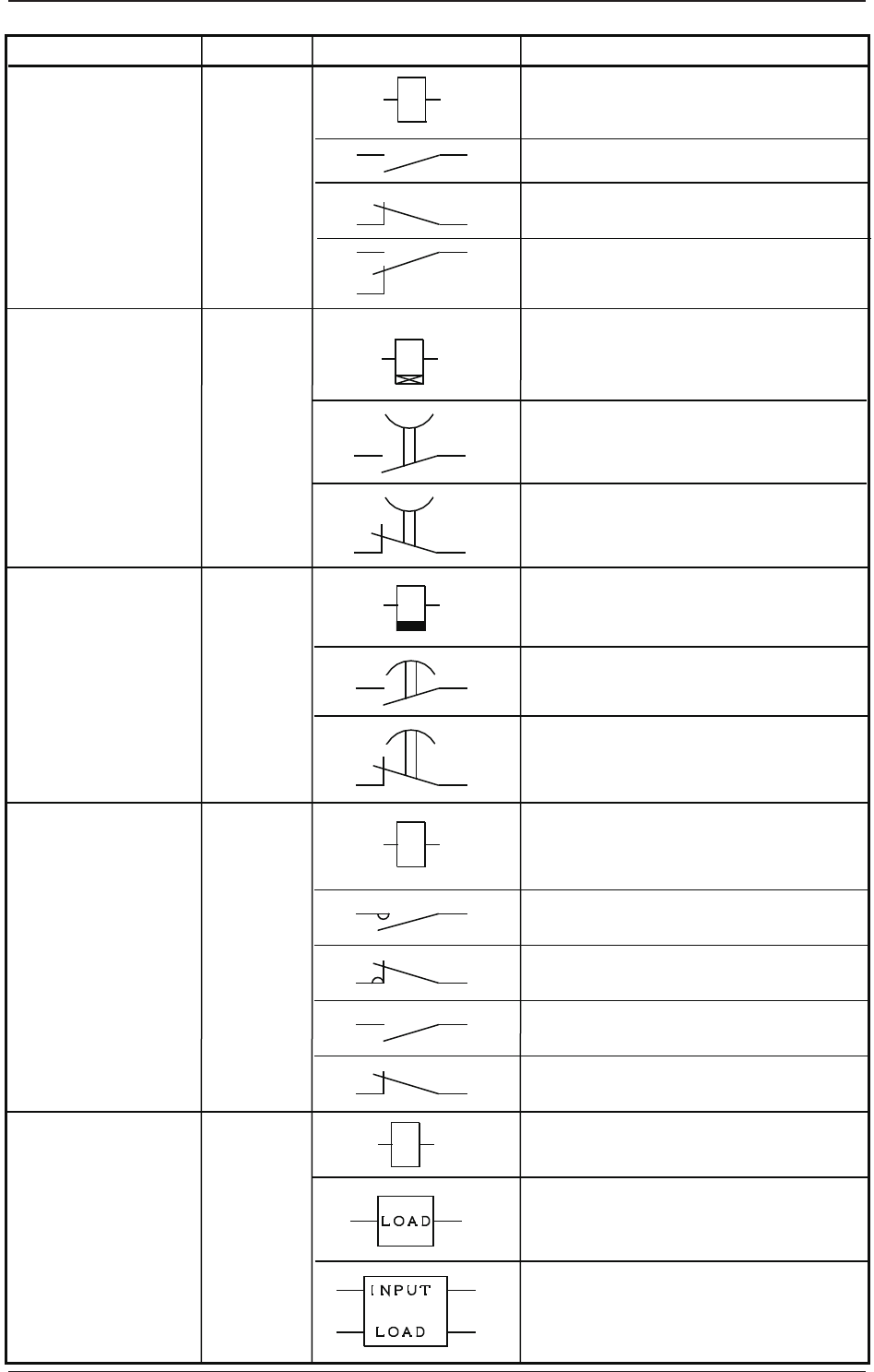
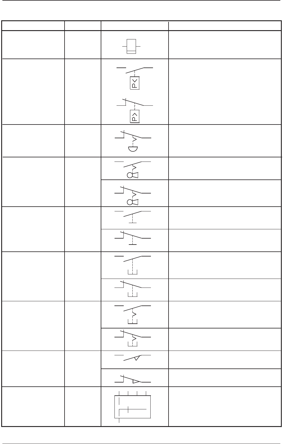
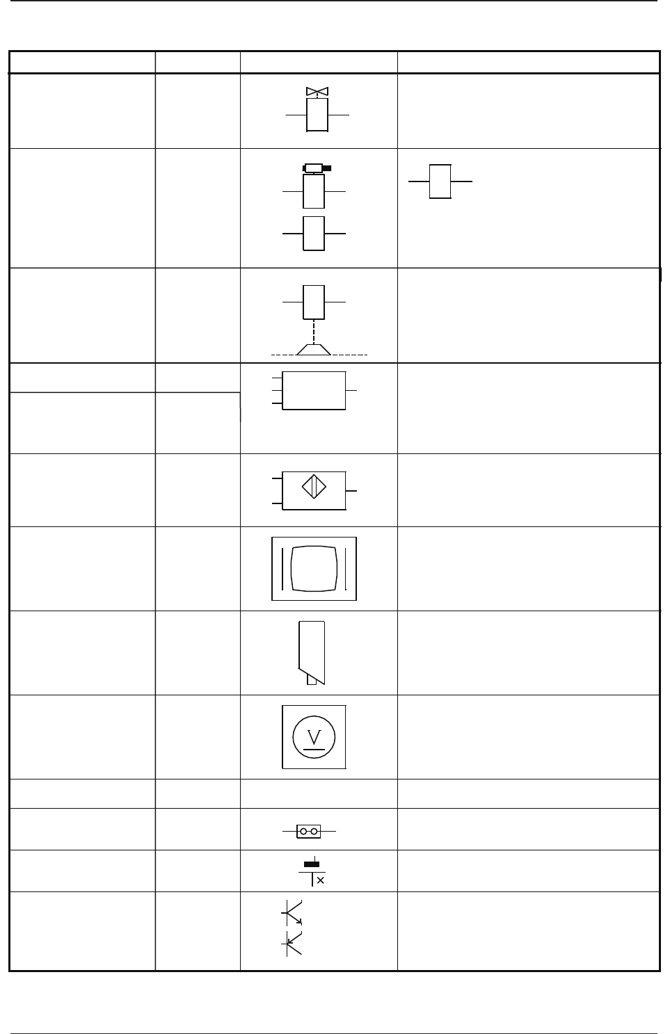
4.1 Electrical and Electronic Symbols
INPUT
LOAD
K
K
K
K
K
Name
Symbols
Graphical Symbols Remarks
Relay
Coil
Contact (a)
Contact (b)
Contact (c)
Coil (ON Delay)
Contact a
(Make Point)
Timer
Contact b
(Break Point)
Coil
(OFF Delay)
Contact a
(Make Point)
Contact b
(Break Point)
Coil
Main Contact (a)
Sub Contact (a)
Main Contact (b)
Sub Contact (b)
A relay may be drawn using both
"INPUT" and "LOAD".
Solid-State Relay
Electromagnetic
Contactor
Timing Relay
(ON Delay)
Timing Relay
(OFF Delay)
5-23
AJK-MLT-ID
0706-002
4.1 Electrical and Electronic Symbols
(a)
(b)
S
S
S
S
S
S
S
S
Name
Symbols
Graphical Symbols Remarks
Cycle Counter
Emergency Stop
Switch
Key Switch
Toggle Switch
Pushbutton Switch
(Alternate)
Safety Door Switch
Limit Switch
Selector Switch
Pushbutton Switch
(Momentary)
Pressure Switch
Contact a
Contact a
Contact b
Contact a
Contact b
Contact b
The theory of contact combination
is described near the graphical
symbol.
Contact a
Contact b
Contact a
Contact b
5-24
AJK-MLT-ID
0706-002
4.1 Electrical and Electronic Symbols
Y
S
B
B
B
P
Y
Battery
Measuring Instrument
Transistor
F
P
V
NPN
Solenoid Valve
Solenoid
Electromagnetic
Brake (OFF Brake)
Position Switch
Vacuum Sensor
Proximity Sensor
Monitor Display
Touch Screen
Photosensor
Camera
Voltmeter
Jumper
The left figure represents a jumper
socket (jumper mounting) in a unit PCB.
The solenoid in the left
figure is used for the
electromagnetic lock-type
door switches.
Name
Symbols
Graphical Symbols Remarks
PNP