OM-1273-004_w.pdf - 第188页
5-25 AJK-ML T-ID 0706-002 4.1 Electrical and Electronic Symbols Name Symbols Graphical Symbols Remarks Noise Filter Servomotor Driver Stepping Motor Driver Speed Control Pack Switching Power Brake Power for Servomotor Li…
5-24
AJK-MLT-ID
0706-002
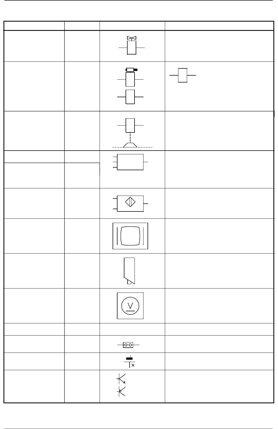
4.1 Electrical and Electronic Symbols
Y
S
B
B
B
P
Y
Battery
Measuring Instrument
Transistor
F
P
V
NPN
Solenoid Valve
Solenoid
Electromagnetic
Brake (OFF Brake)
Position Switch
Vacuum Sensor
Proximity Sensor
Monitor Display
Touch Screen
Photosensor
Camera
Voltmeter
Jumper
The left figure represents a jumper
socket (jumper mounting) in a unit PCB.
The solenoid in the left
figure is used for the
electromagnetic lock-type
door switches.
Name
Symbols
Graphical Symbols Remarks
PNP
5-25
AJK-MLT-ID
0706-002
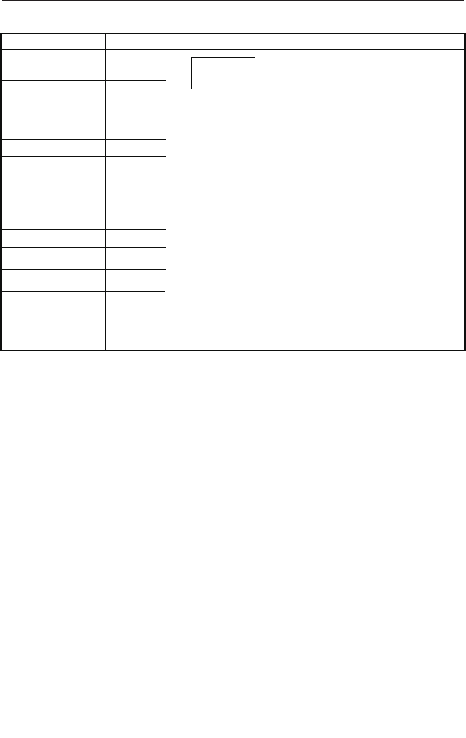
4.1 Electrical and Electronic Symbols
Name
Symbols
Graphical Symbols Remarks
Noise Filter
Servomotor Driver
Stepping Motor Driver
Speed Control Pack
Switching Power
Brake Power for
Servomotor
Lightning Surge
Protector
Unit PCB
Hard Disk Drive
Floppy Disk Drive
The graphical symbol generally
represents a unit.
Different circuit symbols are used
according to the classification of
electrical components.
Z
A
A
A
G
G
F
U
D
D
U
U
Other Units A
Inverter
Converter
AJK-MLT-ID
5-26
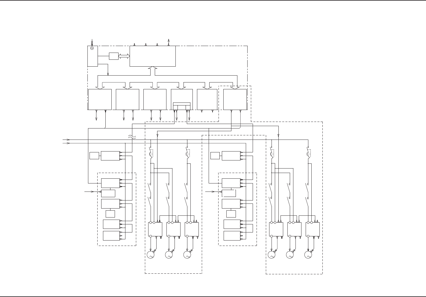
4.2 Electrical Circuit Diagrams
BlockCongurationDrawingL
4.2ElectricalCircuitDiagramsBlockCongurationDrawingL
0706-002 -(M806WBL--5001)
I/OI/OI/O SSCNETSSCNET SSCNET
U83
MR-MC10MR-MC10
U82U84
MR-MC10
I/OSSCNET
U90
MR-MC10
HLS
-X90C1
-X90C2
-K301-K302
-Q101-K101
-K102
-Q201-K201-K202
-K202 -K201 -Q201
-K102
-K101 -Q101
-K302 -K301
CH2 CN1
CH1 CN1
CH2 CN2
CH1 CN2
-X8401
-X8403
-X8301
-X8303
-X8201
-X8203
-X9003
-X9001
HLS
3
M
3
M
3
M
3
M
3
M
3
M
PCI BUS
SDD
U86U85
HLSB-PCI
1 2
HLSC1
+5V
+3.3V
+5V
+12V
-12V
(-5V)
VGACOM1
CPU2-B
U81
/MS
BASE-T
SW+IO(UB26)
16/16 <U>
16/16 <D>
SW+IO(UB26)
IO(UB14)
16/16
32/16
24A
-M01
-M03
-M02
ILB(UA54)
TR-U04:48,49
TR-U05:50
TR-U06:51
TR-U07:52
-M02
-M03
-M01
ILB(UA54)
24A
32/16
16/16
IO(UB14)
SW+IO(UB26)
16/16 <D>
16/16 <U>
SW+IO(UB26)
TR-U04:48,49
TR-U05:50
TR-U06:51
TR-U07:52
AC200V
-24B1L
(L121,221,321)
3φ AC200V
To HUB (U72)
Control (STAGE1)
Feeder Serial
(6 Axes s2ch)
Sensor
Solenoid
Valve,
etc.
Positioning
(UA14)
U09
Relay Circuit
(Safety Circuit,
etc.)
Sensor
Solenoid
Valve, etc
Multi-Layer Tray
(at installation of Stage B)
Traverse
Elevator 2
Elevator 1
With Brake
With Brake
Elevator 1
(Lower)
Elevator 2
(Upper)
Traverse
Multi-Layer Tray
(at installation of Stage B)
(6 Axes s2ch)
(6 Axes s2ch)
(6 Axes s2ch)
Sensor
Solenoid
Valve,
etc.
Positioning
(UA14)
U09
Sensor
Solenoid
Valve, etc
Multi-Layer Tray
(at installation of Stage A)
Multi-Layer Tray
(at installation of Stage A)
Elevator 1
(Lower)
Elevator 2
(Upper)
Traverse
Traverse
Elevator 2
Elevator 1
With Brake
With Brake
Relay Circuit
(Safety Circuit,
etc.)
-A01
-A03-A02
-A02 -A03 -A01