5M-1751-004w_G5S.pdf - 第124页
5OM-1751 1304-001 4-A Chapter 4 Circuit Diagrams This chapter describes the circuit diagrams. As this contains highly sophisticated contents, it should carefully be referred to.
3-22
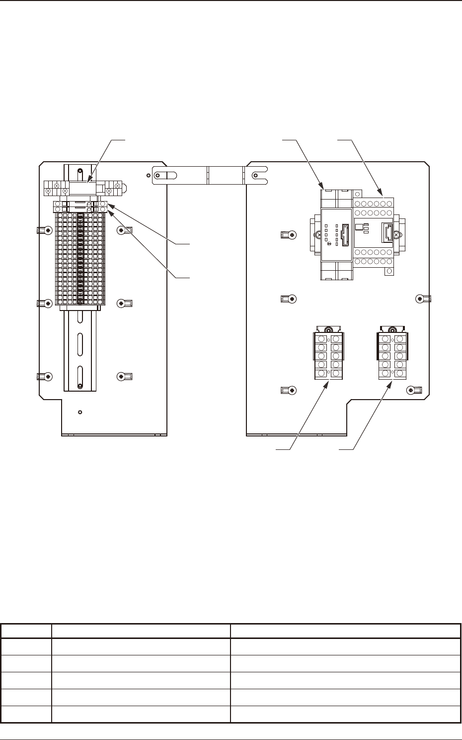
Parts Location
5OM-1751
1305-002
Side Panel (Rear)
K1B
K75 K77
K4 K3
F2(6.3A)
F7(6.3A)
Symbol Name Remarks
K3
Safety Relay (Emergency Stop Switch)
K4
Block #1 Feeder Power ON Relay
K75 Block #1 Feeder Power ON Relay
K77 Block #2 Feeder Power ON Relay
K1B POWER ON Relay

5OM-1751
1304-001 4-A
Chapter 4
Circuit Diagrams
This chapter describes the circuit diagrams.
As this contains highly sophisticated contents, it should carefully be
referred to.

5OM-1751
1304-001 4-B