Printer 710-810 v9 Covers.pdf - 第41页
COVERS PRINTER COVERS Chapter Issue 10, Jul 16 Technical Reference Manual 3.41 Front Panel T o remove the front panel, carry out th e following: 1. Open the front printhead cover . 2. Using a 4mm Allen key , undo the two…
COVERS
PRINTER COVERS
3.40 Technical Reference Manual Chapter Issue 10, Jul 16
Cover Removal Before removing covers ensure that the supplies (air and electrical) have been
isolated from the printer.
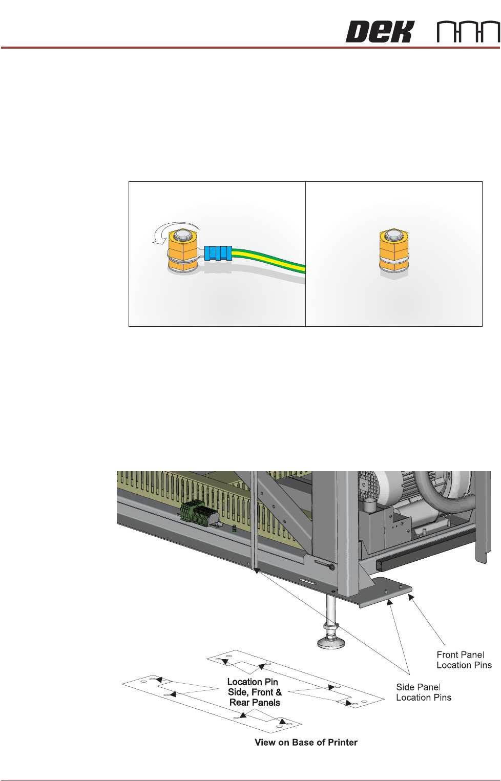
Earth Bonding All external metal surfaces are mechanically and electrically bonded to the
machine earth point. The bonding wire used is identified by its green and yellow
insulation and is commonly used to earth bond throughout.
Using an 8mm spanner, remove the two earth lead securing nuts and detach
the earth lead from the panel.
Care should be taken when removing these links, to ensure that when they are
replaced they are secured tightly and cleanly.
Locating Pins Side, front and rear panels are secured on location pins at the base of the
printer. Plates mounted on each side of the printer (see vignette below) house
the pins; the two centre pins are for the corner panels and the outer pins are for
the side, front and rear panels.
Figure 3-9 Mounting Plates
Earth Stud
COVERS
PRINTER COVERS
Chapter Issue 10, Jul 16 Technical Reference Manual 3.41
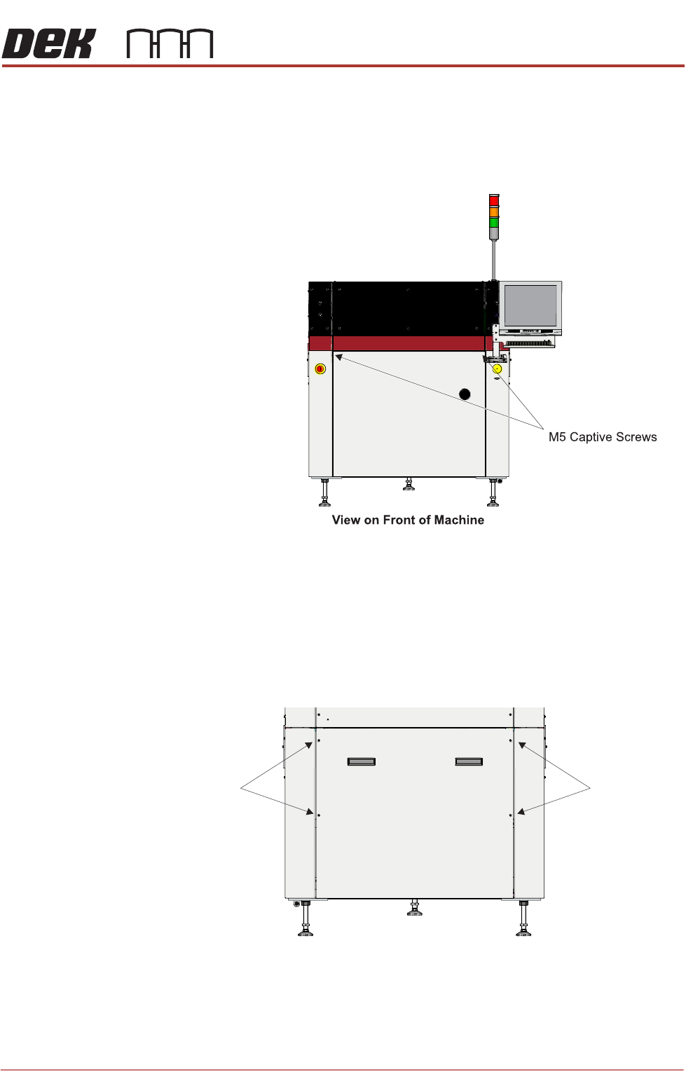
Front Panel To remove the front panel, carry out the following:
1. Open the front printhead cover.
2. Using a 4mm Allen key, undo the two captive screws located on the inside
of the panel.
3. Tilt the top of the panel away from the machine and lift the panel clear of the
location pins that locate the panel to the printer frame, taking care not to
damage the earth cable.
Lower Rear Panel To remove the lower rear panel, carry out the following:
1. Using a 4mm Allen key, undo the four captive screws.
2. Tilt the top of the panel away from the machine and lift the panel clear of the
location pins that locate the panel to the printer frame, taking care not to
damage the earth cable.
M5 Captive
Screws
View on Rear of Machine
M5 Captive
Screws
COVERS
PRINTER COVERS
3.42 Technical Reference Manual Chapter Issue 10, Jul 16
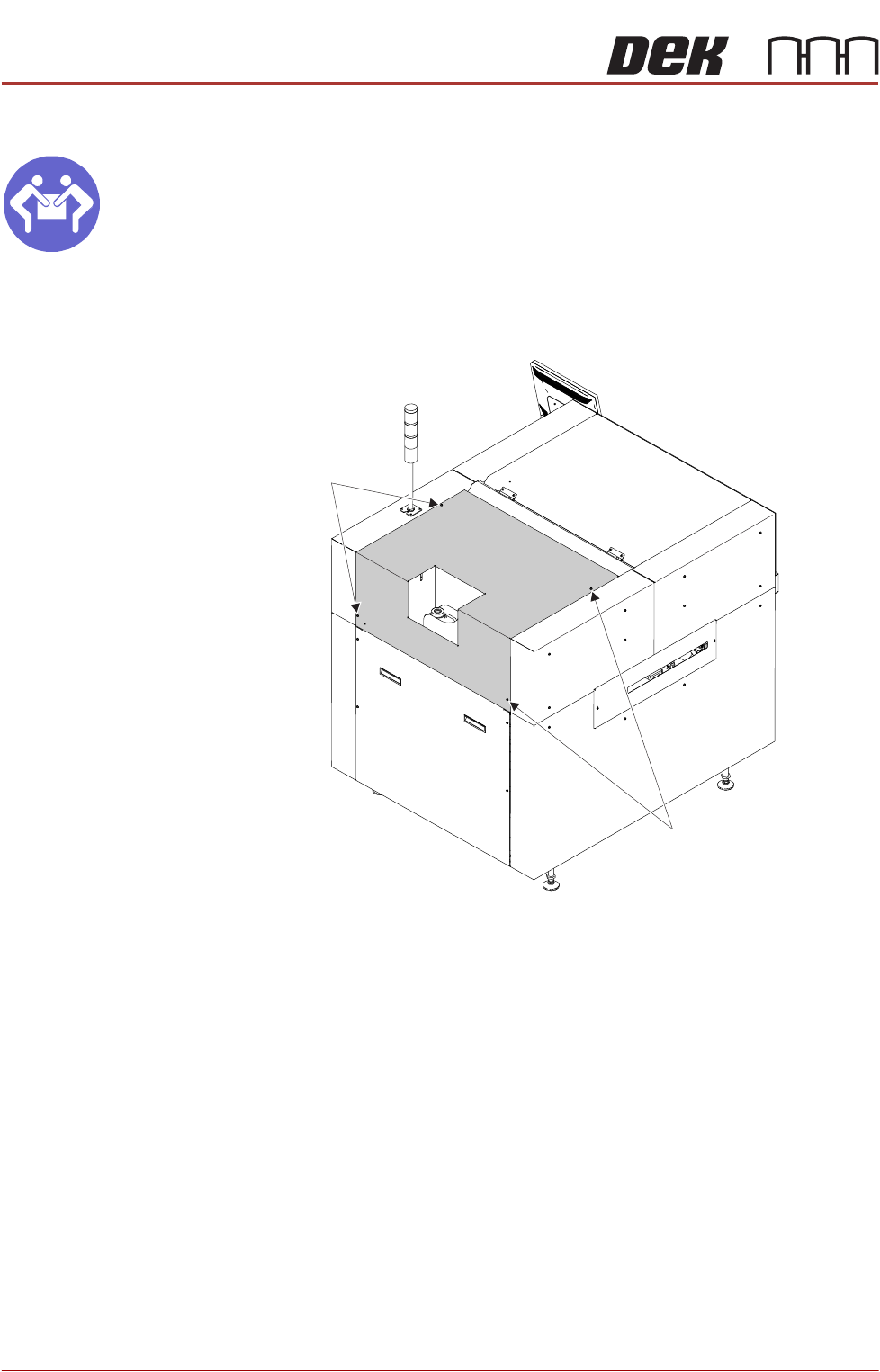
Upper Rear Panel
MANDATORY
HEAVY OBJECT. LIFTING OR RESITING MUST BE UNDERTAKEN BY TWO
PEOPLE.
To remove the upper rear panel, carry out the following:
1. Using a 4mm Allen key, undo the four captive screws.
2. Lift the panel clear of the printer frame, taking care not to damage the earth
cable.
Safety Covers Safety covers are fitted to the side panels to protect personnel from inadvertent
access to the board entry/exit ports.
M5 Captive
Screws
M5 Captive
Screws
Rear Left Quarter View