Printer 710-810 v9 Covers.pdf - 第42页
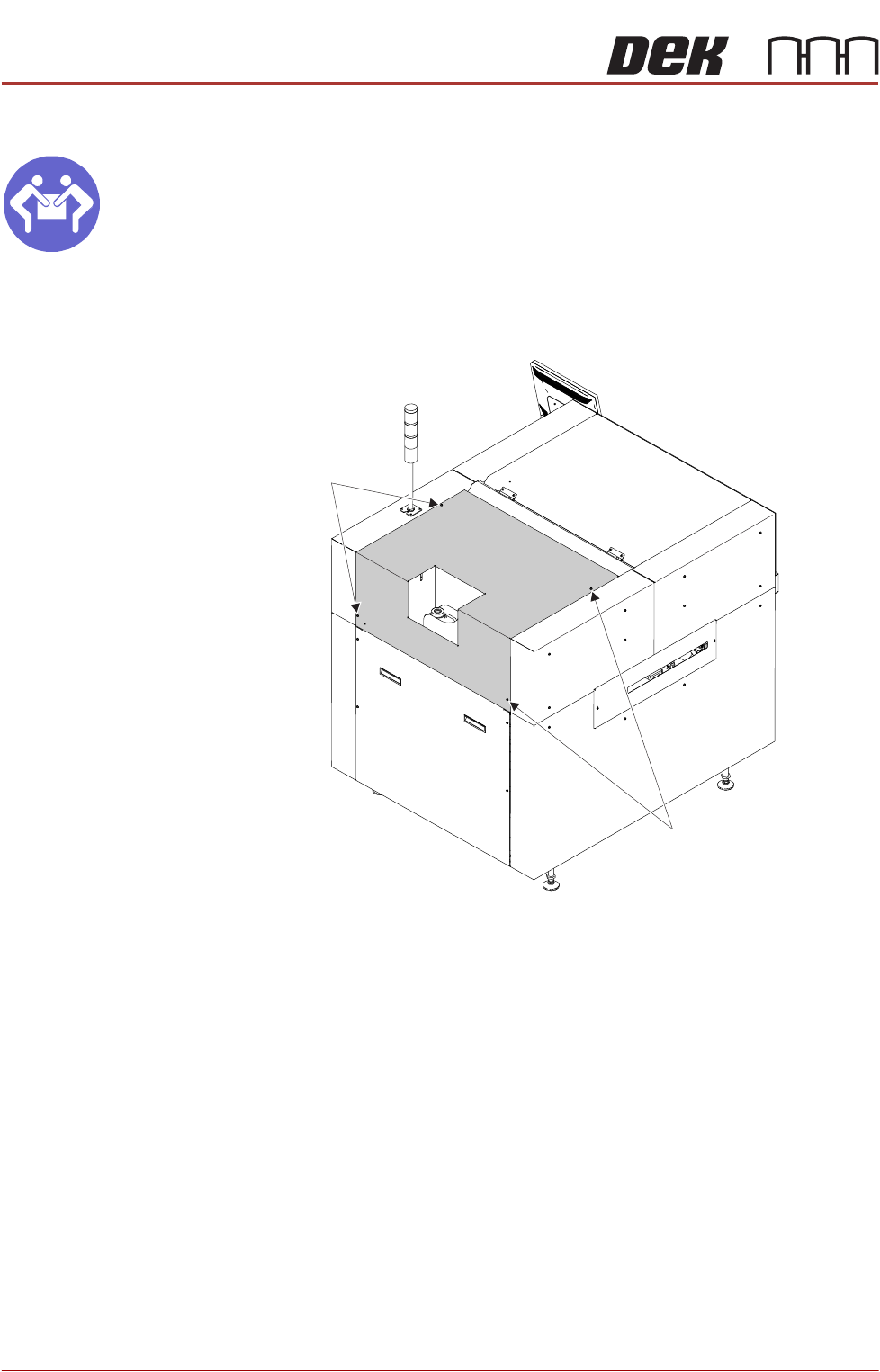
COVERS PRINTER COVERS 3.42 Technical Reference Manual Chapter Issue 1 0, Jul 16 Upper Rear Panel MANDATORY HEAVY OBJECT. LIFTING OR RESITING MUST BE UNDERT AKEN BY TWO PEOPLE. T o remove the upper rear p anel, carry out …
COVERS
PRINTER COVERS
Chapter Issue 10, Jul 16 Technical Reference Manual 3.41
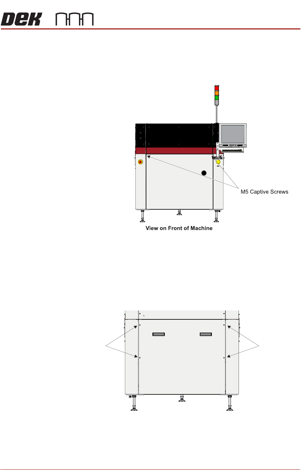
Front Panel To remove the front panel, carry out the following:
1. Open the front printhead cover.
2. Using a 4mm Allen key, undo the two captive screws located on the inside
of the panel.
3. Tilt the top of the panel away from the machine and lift the panel clear of the
location pins that locate the panel to the printer frame, taking care not to
damage the earth cable.
Lower Rear Panel To remove the lower rear panel, carry out the following:
1. Using a 4mm Allen key, undo the four captive screws.
2. Tilt the top of the panel away from the machine and lift the panel clear of the
location pins that locate the panel to the printer frame, taking care not to
damage the earth cable.
M5 Captive
Screws
View on Rear of Machine
M5 Captive
Screws
COVERS
PRINTER COVERS
3.42 Technical Reference Manual Chapter Issue 10, Jul 16
Upper Rear Panel
MANDATORY
HEAVY OBJECT. LIFTING OR RESITING MUST BE UNDERTAKEN BY TWO
PEOPLE.
To remove the upper rear panel, carry out the following:
1. Using a 4mm Allen key, undo the four captive screws.
2. Lift the panel clear of the printer frame, taking care not to damage the earth
cable.
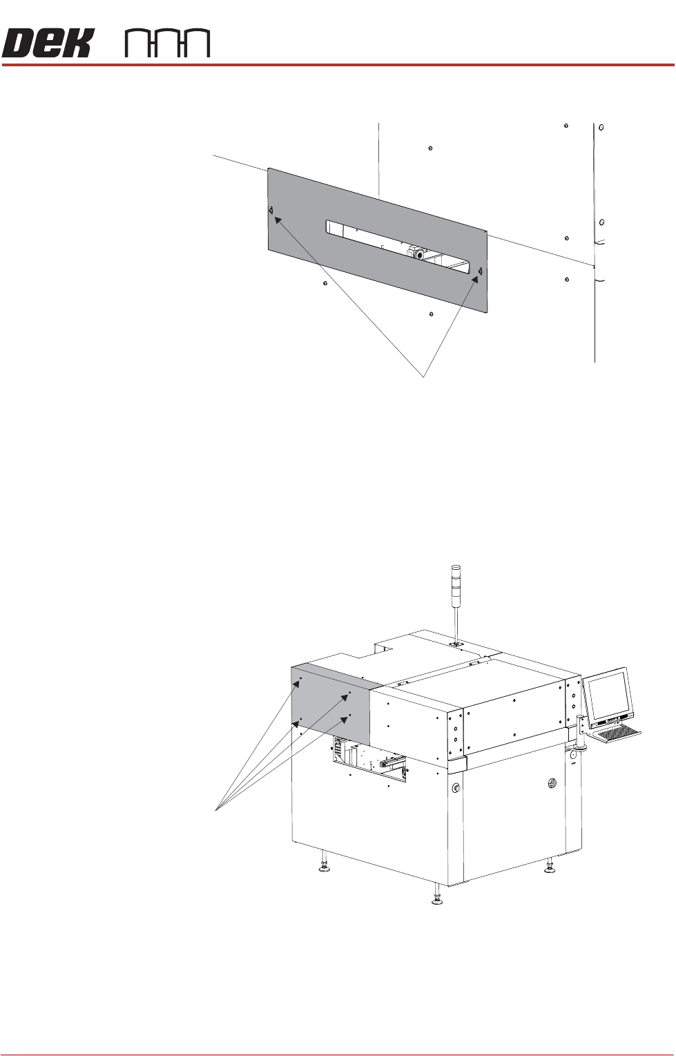
Safety Covers Safety covers are fitted to the side panels to protect personnel from inadvertent
access to the board entry/exit ports.
M5 Captive
Screws
M5 Captive
Screws
Rear Left Quarter View
COVERS
PRINTER COVERS
Chapter Issue 10, Jul 16 Technical Reference Manual 3.43
To remove the safety cover, remove the two securing screws.
Rear Corner Panels To remove the rear corner panels, carry out the following:
1. Remove the Left Hand Safety Cover (as detailed previously).
2. Remove the Right Hand Safety Cover (as detailed previously).
3. Using a 4mm Allen key, undo the appropriate four captive screws.
4. Lift the panel clear of the printer frame, taking care not to damage the earth
cable.
5. Repeat Steps 3 and 4 for the other rear corner panel, if required.
Upper Front Corner
Panels
To remove the upper front corner panels, carry out the following:
1. Open the front printhead cover.
Safety Cover Securing Screws
Front Left Quarter View
Captive Screws