03217917-01-01E By DEK Technical Reference Manual Vol 1_enPDFA.pdf - 第236页
16 TRANSPORT RAILS MODULE 16.4 ADJUSTMENTS AND SETTINGS 236 TECHNICAL REFERENCE MANUAL Vol 1 E By DEK 04/2019 ► Confirm that the amber LED is OFF . If the amber LED is ON , turn the sensitivity control anti- clockwise un…
16 TRANSPORT RAILS MODULE
16.4 ADJUSTMENTS AND SETTINGS
TECHNICAL REFERENCE MANUAL Vol 1 E By DEK 04/2019 235
16.4.2 Board at Left/Right Optos
The board at left/right optos switching threshold can be adjusted by means of a sensitivity control.
This ensures that when a board is fed into the machine (via the transport belts) the sensor output
switches to ON.
To achieve an optimum setting carry out the following procedure:
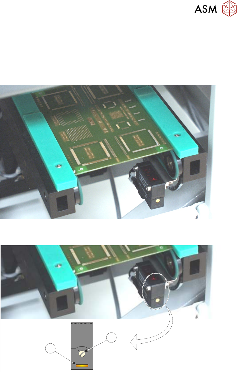
► Place a board on the rails covering the sensor.
► Turn the sensitivity control (1) fully anti-clockwise, ensure that the amber LED (2) is OFF.
+
-
1
2
► Re-adjust the sensitivity control (1) clockwise until the amber LED (2) is ON.
NOTE
If the amber LED is flashing, this indicates a week signal. Re-adjust the sensitivity control.
► Remove the board from the rails and confirm the amber LED is OFF.
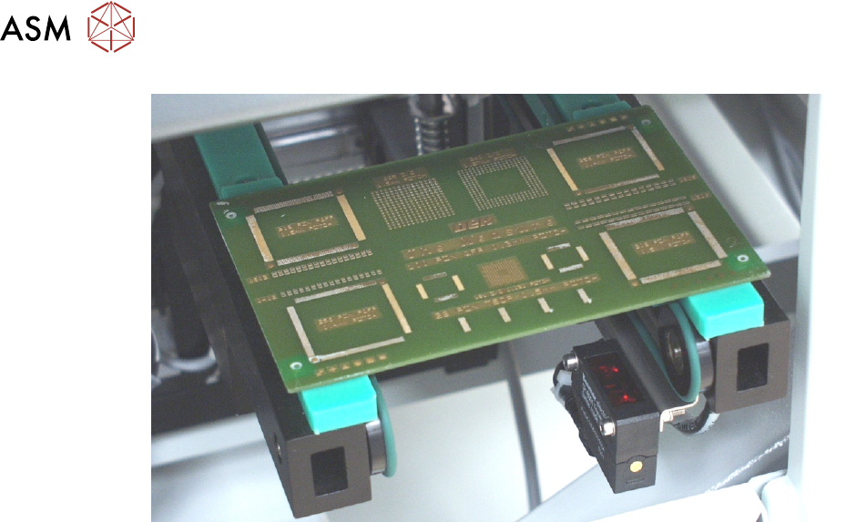
► Turn the board 90° and position back onto the rail system, (so that the board lies on top of the
rail system as shown in the figure below).
16 TRANSPORT RAILS MODULE
16.4 ADJUSTMENTS AND SETTINGS
236 TECHNICAL REFERENCE MANUAL Vol 1 E By DEK 04/2019
► Confirm that the amber LED is OFF. If the amber LED is ON, turn the sensitivity control anti-
clockwise until the amber LED is OFF.
► Remove the board.
► Position the board back on the rail system, as in Step 1, and confirm that the amber LED is
ON.
► If the board has holes or cut-outs, go to continue at next Step. If the board has no holes or
cut-outs remove the board from the rails and confirm that the amber LED is OFF.
► Slide the board backward and forward across the sensor ensuring that the LED is only
triggered by the leading and trailing edges of the board.
► If the LED flickers when encountering holes or cut-outs, turn the sensitivity control clockwise a
further quarter turn.
► Repeat previous two Steps until the correct setting is achieved.
► Remove the board from the rails and confirm that the amber LED is OFF.
► On completion of adjustment, refit the top safety cover removed previously.
16 TRANSPORT RAILS MODULE
16.4 ADJUSTMENTS AND SETTINGS
TECHNICAL REFERENCE MANUAL Vol 1 E By DEK 04/2019 237
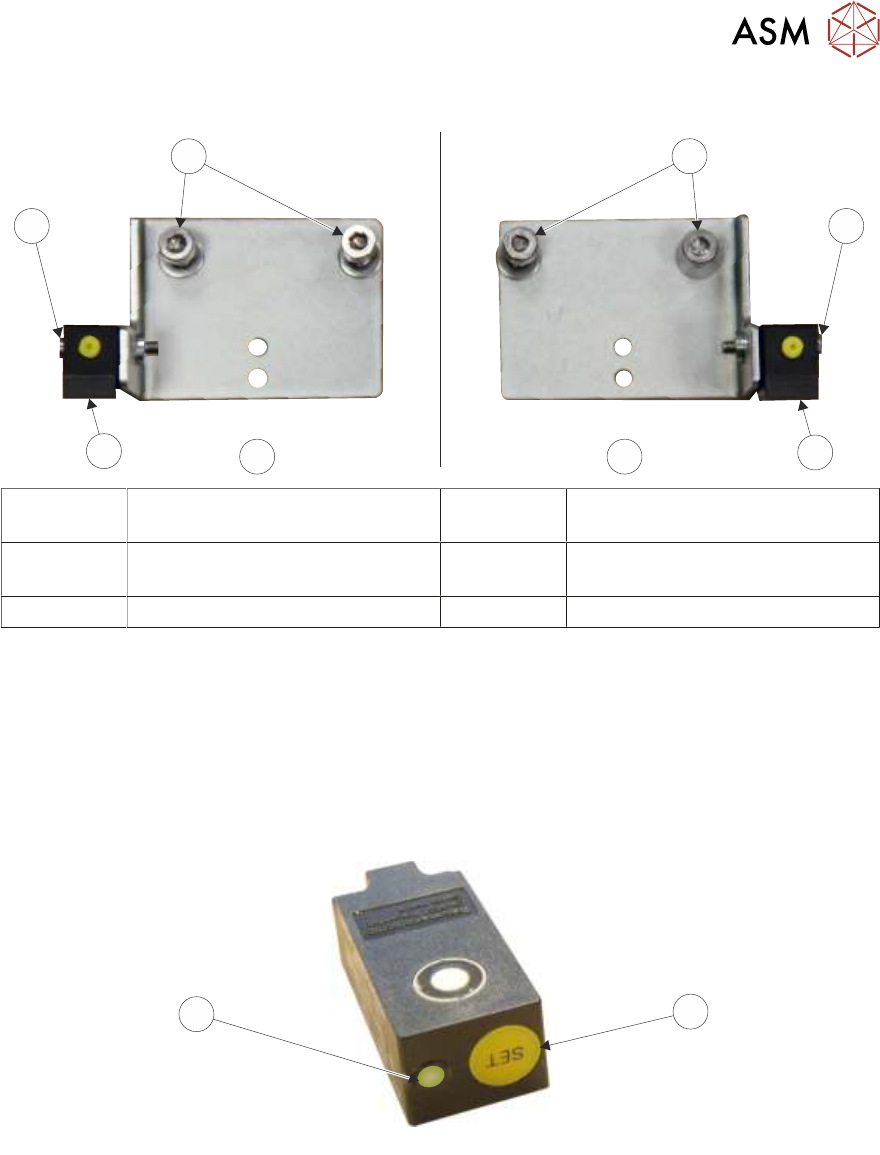
16.4.2.1 Ultrasonic Sensors
5
1
2
3
5
4
3
2
1
1 M4x10 Cap Head Screws 4 View on RH Side of Board at
Right Sensor Bracket
2 M3x16 Cap Head Screw 5 View on LH Side of Board at Left
Sensor Bracket
3 Ultrasonic Sensor
► Remove the top safety cover.
► Ensure that there is no board on the rails or objects near the sensor.
► Press and hold the yellow SET button (1) on the sensor until the status LED (2) flashes green
(approximately 2 seconds).
NOTE
Ensure that use of the Set button (1) is not approached from above the sensor to avoid the sensor
detecting hand movement.
1
2